Video showing the Testing of TSOP1738 with 38 kHz Frequency
The TSOP17XX series of ICs are infrared sensor devices designed for sensing infrared frequencies only with a specific range of modulated frequency, and interpreting them into a proportionate magnitude of electrical pulses at the output.
This is specifically done to make the sensor immune to other forms of infrared signals present in the atmosphere such as from sunlight, fluorescent tube lights etc.
This feature allows the device to be used in various forms of remote control applications without worrying about any form of external false triggering.
The TSOP1738 series ICs are commonly used in many infrared remote control systems, such TV, remote handsets, or set top box remote controls etc.
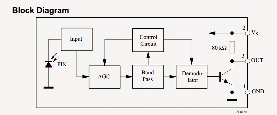
The lead frame is used to assemble the preamplifier and PIN diode along with the IR filter which is a design of the epoxy package.
A microprocessor is used to decode the output signal directly which is demodulated in an easy way.
The TSOP1738 series is considered as the standard series for the infrared remote control receiver which in turn supports all the important transmission codes.
Remote IR Sensor Pinout Details
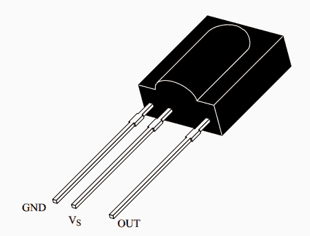
Available IR Sensor Types
TSOP1730 - 30 kHz TSOP1733 - 33 kHzTSOP1736 - 36 kHz TSOP1737 - 36.7 kHzTSOP1738 - 38 kHz TSOP1740 - 40 kHzTSOP1756 - 56 kHz
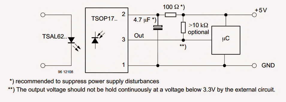
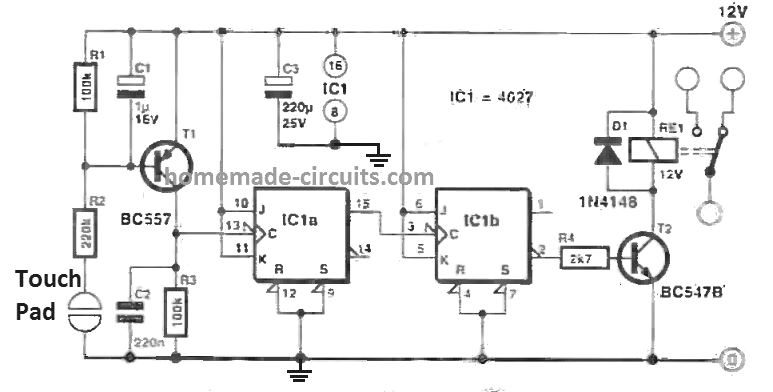
Typical application circuit and connections are shown below
Main Electrical Specifications
The TSOP17XX series provides two benefits of preamplifier an photo detector in a single package
An internal filter is present for the facilitation of PCM frequency
TSOP 17XX series provides an enhanced shielding against the disturbances produced by the various kinds of electrical fields
It is also compatible to TTL and CMOS
The output active given by the TSOP17… series is low
It consumes low power
The immunity provided by TSOP17… series against ambient light is high
TSOP17XX series enables a continuous data transmission of up to 2400 bps
The device provides 10 cycles/burst which is considered as the most appropriate burst length
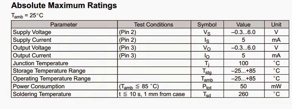
Absolute Maximum Rating
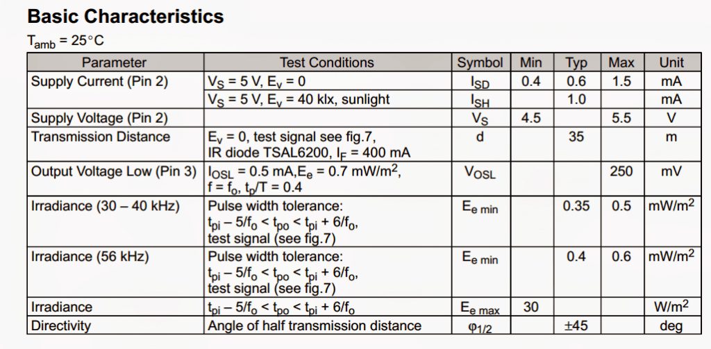
Basic Characteristics
How TSOP1738 IC Works
The circuit design of the TSOP1738 series has been designed to work in such a way that it avoids any kind of output pulses which occurs unexpectedly due to the signal disturbances and noise.
In order to suppress or avoid this noise and signal disturbances, the TSOP1738 series works by using different applications such as an integrator stage, a band pass filter, and an automatic gain control.
The distinction between a disturbance signal and a data signal can be carried out by reading the burst length, carrier frequency, and the duty cycle.
The criteria or conditions which a data signal needs to fulfill are as follows:
The carrier frequency of the data signal needs to be close to the band pass filter’s center frequency such as at a frequency of 38kHz
The burst length of a data signal must be either 10 cycles/burst or longer than that
A gap time after each burst which usually ranges between 10 cycles to 70 cycles for a data signal should necessarily be at the minimum of 14 cycles.
For every burst of the data signal which occurs for duration of more than 1.8ms, the corresponding gap time is essential at some time of the process within the data stream.
The length of this gap time must be at least equal to the burst length.
In a data signal, approximately 1400 short burst can be received every second on a continuous basis
The various data formats which are considered suitable are: Toshiba Micom Format, NEC Code, RC5 Code, R-2000 Code, Sharp Code, RC6 code, and SIRCS (Sony Format).
The data signal can be received in a TSOP17xx series even when a disturbance signal is applied to the TSOP17xx series.
But, the sensitivity in this case is reduced to a specific level where the occurrences of unexpected pulses can happen.
The different disturbance signals, which can be suppressed when TSOP17xx series is used, are:
DC light which can range from a simple tungsten ball to the more powerful natural resource of sunlight
The signal which are continuously received at 38kHz or signal received at frequency other than 38kHz
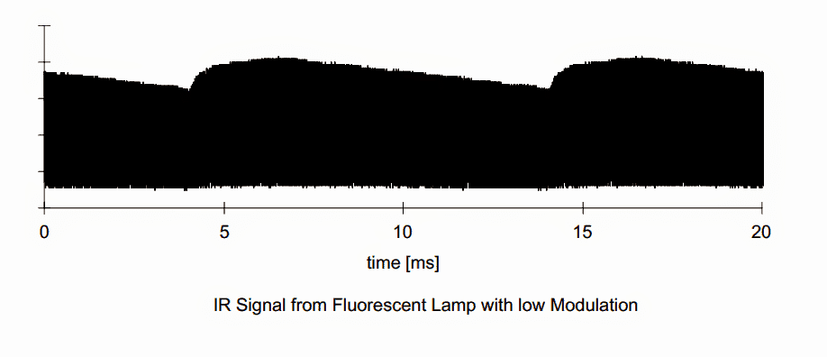
The signals which are received from fluorescent lamps which consist of electronic ballast. The figure given below shows a sample of how the signal modulation occurs.


Questions & Answers
Hi Swagatam,
I am working with a TSOP 34838 circuit and wonder if it is possible to connect more than one TSOP 34838 in a circuit to cover a 360 degree area. If so, do I need blocking diode to protect one TSOP 34838 from the other TSOP 34838? I am limited by space and would prefer not to use any blocking diodes. Thanks!
Hi Norman,
If you are connecting the devices in parallel then I think only the OUT pin of the TSOP sensors will require a 1N4148 diode for isolation across each other. Cathode will go to the OUT pin and anode will terminate as the output.
Hello
Sir my name is Deepak from pune, I want remote control decoder and apply the same frequency on the same device, and it works on mostly on 36 khz to 40 khz.
Is it possible to make remote that works on any ir gadget.
If yes please let me know.
Deepak, the TSOP will only respond only to frequencies around 38 kHz, if you want the receiver to respond to all IR frequencies, then you can use an ordinary photo diode instead of TSOP
Alguem sabe me responder qual ligação deve ser feita para que eu posso usar esse sensor como detector de obstaculo? (Vou usar no Arduíno). Obg
on the serial monitor
i am using tsop 1738 sensor with arduino , but every time i press the same button on the remote control , i get different sequence , what should i do so that when i press a particular button on remote , i get a particular sequence , please help me