• Skip to main content
  • Skip to primary sidebar

Homemade Circuit Projects

Need circuit help? Post them in the comments! I've answered over 50,000!

Blog | Categories | About | Contact | Calculators-online
You are here: Home / Datasheets and Components / 50 Amp Transistor MJ11032, MJ11033 Datasheet, Pinout

50 Amp Transistor MJ11032, MJ11033 Datasheet, Pinout

Last Updated on May 19, 2021 by Swagatam 5 Comments

If you are looking for high current transistors in the range of 50 amps with a complementary pair, then you can try these Darlington transistors MJ11032 and MJ11033. The MJ11032 transistor is a Darlington NPN power transistor while the MJ11033 is its complementary PNP transistor which is also a Darlington power BJT.

Table of Contents
  • Main features
  • Pinout Diagram
  • Maximum Tolerable Rating

Main features

The main features of the MJ11032 MJ11033 complementary Darlington pair transistors are as given below:

  • High DC current gain of 1000 hFE minimum when the collector is operated at 25 amp DC
  • DC current gain capacity may be reduced to 400 hFE, if the collector current rises to 50 amp DC
  • The transistor is able to handle up to 100 amp if the current is in the pulsed manner
  • Internal protection diode are provided to the transistors for protection against inductive transients.
  • The monolithic design of the BJTs also include internal base/emitter shunt resistor to limit maximum base current.
  • The 50 amp transistors are rated to handle junction temperatures as high 200 degrees Celsius
  • Total power dissipation or power handling capacity without heatsink is 300 watts
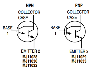
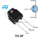
Pinout Diagram

The pinout connections for the 50 amp MJ11032, MJ11033 complementary transistors can be seen in the following images:

warning message: electricity is dangerous, proceed with caution
50 amp Darlington BJT pinout
50 amp transistor

Maximum Tolerable Rating

The maximum tolerable rating of transistors mainly refers to the maximum amount of voltage and current the devices can tolerate at 25 degrees Celsius ambient temperature. The following table shows the maximum tolerable voltage and current limits of the 50 amp transistors MJ11032, MJ11033.

50 amp transistor maximum rating compressed

Complete datasheet can be downloaded from the following link

MJ11032, MJ11033 DatasheetDownload

You'll also like:

  • 1.  How Shunt Regulator TL431 Works, Datasheet, Application
  • 2.  TIP127 Datasheet [100V, 5 Amp PNP Darlington Transistor]
  • 3.  IC 4070 Datasheet, Pinout Working, Truth Table, Electrical Characteristics
  • 4.  400V 40A Darlington Power Transistor Datasheet Specifications
  • 5.  IC 4018 Datasheet, Pinout Function Explained
  • 6.  IC 4011 Datasheet, Pinout, Applications

About Swagatam

I am an electronics engineer with over 15 years of hands-on experience. I am passionate about inventing, designing electronic circuits and PCBs, and helping hobbyists bring their projects to life. That is why I founded homemade-circuits.com, a website where I share innovative circuit ideas and tutorials. Have a circuit related question? Leave a comment.... I guarantee a reply!

Previous Post: « White Noise and Pink Noise Generator Circuit
Next Post: Simple IC 4017 Circuits »

Reader Interactions

Comments

  1. B. Tschacher says

    January 4, 2024 at 11:46 pm

    Hey, I have a project that needs a couple pairs of tilt switches to limit actuators and I’ve been looking at some, mercury and ball and whatever is listed. My problem is most are rated for small currents and I want to be able to handle up to 10 amps so I’ve been trying to figure how to construct a transistor amplifier these tilt switches can turn on and off. Been confusing me as to how this can be down. You have any suggestions?

    Reply
    • Swagatam says

      January 5, 2024 at 8:56 am

      Hello Bret,
      You can check out the following article. The first diagram shows how to use a tilt switch with a transistor to operate the higher current load. The transistor rating can be upgraded as per the load requirement. Let me know if you have any further doubts.

      Reply
  2. Bret Tschacher says

    July 9, 2023 at 4:30 am

    Hi, I was just looking at this component and also looking at the shcematic you post on the 24v to 12v converter using the LM78S40 and considering using a collection of these as the high power switches. My big question is how much current it would take to trigger say 5 of these in parallel from the IC to the base of all the Q’s, since BJT’s are current driven instead of voltage as would be by using MOSFET’s. Am I going to need to add in a current amp and load sharing R’s to get all the Q’s to firing evenly. I need a Vreg that will give me around 50 to 70amps.

    Reply
    • Swagatam says

      July 9, 2023 at 9:29 am

      Hi, Although I do not know the output current specification of the LM78S40, whatever it is, should be sufficient for switching the above 50 amp transistors since these are are Darlington type with high current gain.

      Reply
  3. J. Schwender says

    June 28, 2021 at 4:10 pm

    Note that Tc is case temperature, not ambient. So 300 W is good for perfect cooling, not without heat sink.

    Reply

Need Help? Please Leave a Comment! We value your input—Kindly keep it relevant to the above topic! Cancel reply

Your email address will not be published. Required fields are marked *

Primary Sidebar

Subscribe to New Circuit Ideas

Categories

  • Arduino Projects (87)
  • Audio and Amplifier Projects (132)
  • Automation Projects (17)
  • Automobile Electronics (101)
  • Battery Charger Circuits (83)
  • Datasheets and Components (104)
  • Electronics Theory (143)
  • Free Energy (37)
  • Games and Sports Projects (11)
  • Grid and 3-Phase (19)
  • Health related Projects (25)
  • Home Electrical Circuits (12)
  • Indicator Circuits (14)
  • Inverter Circuits (87)
  • Lamps and Lights (142)
  • Meters and Testers (69)
  • Mini Projects (46)
  • Motor Controller (64)
  • Oscillator Circuits (27)
  • Pets and Pests (15)
  • Power Supply Circuits (108)
  • Remote Control Circuits (50)
  • Security and Alarm (64)
  • Sensors and Detectors (101)
  • Solar Controller Circuits (59)
  • Temperature Controllers (42)
  • Timer and Delay Relay (49)
  • Transmitter Circuits (29)
  • Voltage Control and Protection (37)
  • Water Controller (36)

Calculators

  • Battery Back up Time Calculator
  • Capacitance Reactance Calculator
  • IC 555 Astable Calculator
  • IC 555 Monostable Calculator
  • Inductance Calculator
  • LC Resonance Calculator
  • LM317, LM338, LM396 Calculator
  • Ohm’s Law Calculator
  • Phase Angle Phase Shift Calculator
  • Power Factor (PF) Calculator
  • Reactance Calculator
  • Transistor Astable Calculator
  • Transistor base Resistor Calculator
  • Voltage Divider Calculator
  • Wire Current Calculator
  • Zener Diode Calculator
  • Filter Capacitor Calculator
  • Buck Converter Calculator
  • Boost Converter Calculator
  • Solar Panel, Inverter, Battery Calculator
  • Wire Current Calculator
  • SMPS Transformer Calculator
  • IC SG3525, SG3524 Calculator
  • Inverter LC Filter Calculator

People Also Search

555 Circuits | 741 Circuits | LM324 Circuits | LM338 Circuits | 4017 Circuits | Ultrasonic Projects | SMPS Projects | Christmas Projects | MOSFETs | Radio Circuits | Laser Circuits | PIR Projects |

Recent Comments

  • Swagatam on Contact
  • KRAB Babu on Contact
  • Swagatam on How Shunt Regulator TL431 Works, Datasheet, Application
  • SA on How Shunt Regulator TL431 Works, Datasheet, Application
  • Swagatam on Timer Based Cell Phone Charger Circuit

Company

  • Privacy Policy
  • Cookie Policy
  • About Me
  • Contact
  • Disclaimer
  • Copyright
  • Videos
  • Sitemap

Social Profiles

  • Twitter
  • YouTube
  • Instagram
  • Pinterest
  • My Facebook-Page
  • Quora
  • Stack Exchange
  • Linkedin
  • © 2025 · Swagatam Innovations