• Skip to main content
  • Skip to primary sidebar

Homemade Circuit Projects

Need circuit help? Post them in the comments! I've answered over 50,000!

Blog | Categories | About | Contact | Calculators-online
You are here: Home / Lamps and Lights / Single IC Dimmable Ballast Circuit

Single IC Dimmable Ballast Circuit

Last Updated on January 1, 2024 by Swagatam 2 Comments

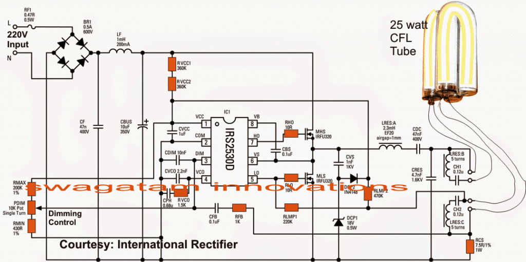
In this post I have explained a simple 25 to 36 watt ballast circuit which can used for all fluorescent tube applications within the allocated range.

Table of Contents
  • The Preheater Stage
  • The Charge Pump Circuit
  • The Dimmer Stage
  • Ensuring 100% Ignition

warning message: electricity is dangerous, proceed with caution
electronic ballast circuit with dimmable feature

The circuit of the proposed electronic fluorescent ballast may be understood through the following discussion:

The Preheater Stage

The half-bridge stage comprising the two mosfets are triggered by the IC for initiating the required preheating of the tube filaments and for striking the tube into complete illumination.

An instant start is facilitated by the presence of RVCC1 and RVCC2 by providing the required start-up current to the positive line of the circuit.

The Charge Pump Circuit

In the meantime the charge pump section made by CSNUB, DCP1 and DCP2 takes control of the situation while the IC begins oscillating.

LRES and CRES form the resonant tank circuit and are responsible for generating a high voltage for the transition functions useful for the igniting the tube. It also helps to provide a low-pass filtering intended for the dimmable action of the tube.

You would also witness a DC blocking capacitor CDC intended to keep the lamp current at an AC potential which is important for preventing mercury merger and lamp blackening at the ends as a result. The feature ensures longer lamp life with great intensities.

LRES:A,B are the secondary winding inside in the resonant coil which are included for optimal preheating of the filaments and also for implementing the featured dimmable actions.

It also allows the use of a single resistor RCS for the required current sensing by extracting an isolated current supply from the filament source. This current sensed across RCS is applied to the DIM pinout of the IC via a feedback loop made by a resistor, capacitor network: CFB and RFB.

The Dimmer Stage

The dimming network includes a potentiometer control which essentially provides a varying reference voltage to the DIM pin of the IC enabling the dimming of the lamp to any desired level manually.

RLMP1 and RLMP2 are positioned for detecting the presence of the lamp that may be used at the output.

As soon as the lamp connection is detected by this stage the circuit initiates the above discussed functions, instantly illuminating the tube to its optimal intensity.

Ensuring 100% Ignition

In addition to the above, the IC IRS2530D has some outstanding in-built features such as 100% ensured ignition of the connected tube and a sustained constant illumination of the tube even under low voltage conditions from the mains input. Moreover all these are achieved by using very few number of components.

Thanks to International Rectifier for providing us with the discussed single chip electronic ballast circuit.

Circuit Diagram

electronic ballast circuit 1024x510 1

You'll also like:

  • 1.  Make this LED Driver Circuit for Backlighting Small LCD Screens
  • 2.  Make this Plasma Ball Circuit
  • 3.  Electric Match (Ematch) Circuit Firework Ignitor
  • 4.  How to Drive High Watt LEDs with Arduino
  • 5.  How to make simple a LI-FI (Light Fidelity) Circuit
  • 6.  How to Make Car LED Bulb Circuit

About Swagatam

I am an electronics engineer with over 15 years of hands-on experience. I am passionate about inventing, designing electronic circuits and PCBs, and helping hobbyists bring their projects to life. That is why I founded homemade-circuits.com, a website where I share innovative circuit ideas and tutorials. Have a circuit related question? Leave a comment.... I guarantee a reply!

Previous Post: « 4 Automatic Staircase Lamp Controller Circuits Explained
Next Post: Grid-tie Inverter (GTI) Circuit Using SCR »

Reader Interactions

Comments

  1. P Swarup says

    June 12, 2018 at 2:42 am

    Hi Swagatam,

    I had been reading your posts and experimenting a bit. Currently i am stuck with following idea – and hope you can get me out of it.

    Consider this to measure a fixed distance divided in 10 equal parts (a voltage divider with say 10 1k resistors in series and 10v DC applied produces drop of 1v per resistor).
    When a body moves from say 0 to any of above resistor contact, it basically reads the voltage on that contact – thus deriving the distance covered.
    I wanted to display the distance covered by a LED bar graph, using LM3914 – but i am not able to detect the voltage drops accurately and so the distance covered. Tried several calculations on Rref, Rhi, Rlo – but all in vain; sometimes even distance covered for 4 blocks shows 5 bars while sometimes distance of 9 blocks shows 8 bars.
    Lost in accurate translations of the resistor values within the LM3914 IC.

    Your help is appreciated. Any suggestions to improve it or a new design to measure distance on equidistant plane would be helpful.

    Thanks.

    Reply
    • Swagatam says

      June 12, 2018 at 10:34 am

      Hi Swaroop, the response of LM3915 IC at its pin#5 will be quite linear, so first determine the resistor range that would cause the output to increment from 1 to 10 corresponding to the 10 resistors.

      You can do it by connecting a 10K preset’s outer leads across pin#5 and ground of the IC, and then attaching the center pin of the preset with the 10V source via a 1K resistor. Now you may vary the preset and check at what resistor values the LEDs sequence across the output pins. For increasing the accuracy you could try a 100K preset or pot instead of a 10K perset.

      Reply

Need Help? Please Leave a Comment! We value your input—Kindly keep it relevant to the above topic! Cancel reply

Your email address will not be published. Required fields are marked *

Primary Sidebar

Subscribe to New Circuit Ideas

Categories

  • Arduino Projects (87)
  • Audio and Amplifier Projects (132)
  • Automation Projects (17)
  • Automobile Electronics (101)
  • Battery Charger Circuits (83)
  • Datasheets and Components (104)
  • Electronics Theory (143)
  • Free Energy (37)
  • Games and Sports Projects (11)
  • Grid and 3-Phase (19)
  • Health related Projects (25)
  • Home Electrical Circuits (12)
  • Indicator Circuits (14)
  • Inverter Circuits (87)
  • Lamps and Lights (142)
  • Meters and Testers (69)
  • Mini Projects (46)
  • Motor Controller (64)
  • Oscillator Circuits (27)
  • Pets and Pests (15)
  • Power Supply Circuits (108)
  • Remote Control Circuits (50)
  • Security and Alarm (64)
  • Sensors and Detectors (101)
  • Solar Controller Circuits (59)
  • Temperature Controllers (42)
  • Timer and Delay Relay (49)
  • Transmitter Circuits (29)
  • Voltage Control and Protection (37)
  • Water Controller (36)

Calculators

  • Battery Back up Time Calculator
  • Capacitance Reactance Calculator
  • IC 555 Astable Calculator
  • IC 555 Monostable Calculator
  • Inductance Calculator
  • LC Resonance Calculator
  • LM317, LM338, LM396 Calculator
  • Ohm’s Law Calculator
  • Phase Angle Phase Shift Calculator
  • Power Factor (PF) Calculator
  • Reactance Calculator
  • Transistor Astable Calculator
  • Transistor base Resistor Calculator
  • Voltage Divider Calculator
  • Wire Current Calculator
  • Zener Diode Calculator
  • Filter Capacitor Calculator
  • Buck Converter Calculator
  • Boost Converter Calculator
  • Solar Panel, Inverter, Battery Calculator
  • Wire Current Calculator
  • SMPS Transformer Calculator
  • IC SG3525, SG3524 Calculator
  • Inverter LC Filter Calculator

People Also Search

555 Circuits | 741 Circuits | LM324 Circuits | LM338 Circuits | 4017 Circuits | Ultrasonic Projects | SMPS Projects | Christmas Projects | MOSFETs | Radio Circuits | Laser Circuits | PIR Projects |

Recent Comments

  • Swagatam on How Shunt Regulator TL431 Works, Datasheet, Application
  • SA on How Shunt Regulator TL431 Works, Datasheet, Application
  • Swagatam on Timer Based Cell Phone Charger Circuit
  • Nitesh Agrawal on Timer Based Cell Phone Charger Circuit
  • Swagatam on Timer Based Cell Phone Charger Circuit

Company

  • Privacy Policy
  • Cookie Policy
  • About Me
  • Contact
  • Disclaimer
  • Copyright
  • Videos
  • Sitemap

Social Profiles

  • Twitter
  • YouTube
  • Instagram
  • Pinterest
  • My Facebook-Page
  • Quora
  • Stack Exchange
  • Linkedin
  • © 2025 · Swagatam Innovations