In this post I have explained a simple 220 V to 220V DC online UPS inverter circuit. The idea was requested by Mr. Taiye.
Technical Specifications
I intend to build a 1000 watt UPS with a different concept (inverter with high voltage input dc).
I will use a battery bank of 18 to 20 sealed batteries in series each 12 volts/ 7 Ah to give a 220+ volts storage as input to a transformerless inverter.
Can you suggest a simplest possible circuit for this concept which should include a battery charger + protection and auto switching by mains failure. Later I will include a solar power input too.
Warning: The above circuit is not isolated from mains AC, and therefore is extremely dangerous to touch in the powered and open condition. You should be extremely careful while building and testing this circuit, and make sure to take the necessary safety precautions. The author cannot be held responsible for any mishap due to any negligence by the user
The Design
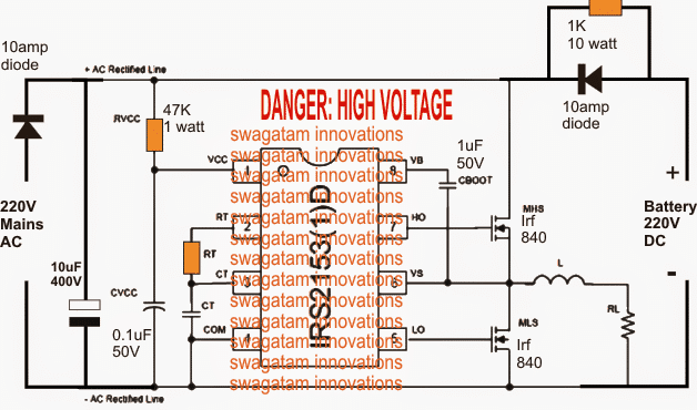
A very simple design can be witnessed in the above diagram for the proposed 220V DC UPS inverter circuit. Thanks to the IC IRS2153 from International Rectifiers which has everything included inside one package for the required implementation..
Basically, the IC is a specialized half bridge mosfet driver unit having all the required safety parameters built-in, so that we don't have to bother about these while building a customized half-bridge inverter circuit.
As can be seen in the diagram, there's hardly anything complicated, it's just about integrating the mains input and an equivalently rated battery at the other side for implementing a hassle free 220V online UPS circuit which is solid state in design, noiseless, and transformerless.
The Rt and Ct are appropriately selected for achieving the required 50 or 60Hz frequency for the output load.
It may be done by using the following formula:
f = 1/1.453× Rt x Ct, where Ct will be in Farads, Rt in Hz, and f in Hz.
L1 may be selected with some experimentation so that the square wave harmonics can be controlled to some favorable extent.
Here, to avoid complication an automatic over charge cut off feature is not included, rather a trickle charge feature is opted for charging the battery. This may take a relatively longer time for the battery to get charged but the dangers of over charge is eliminated and reduced to safe levels.
The 1K 10 watt resistors determines the charging rate for the battery, optionally the battery could be charged through a suitable external charger circuit.
UPDATE:
Since a half bridge driver IC is used in the above design, the output will be a half wave output, meaning for a 310V DC input the output will be around 130V RMS, although the peaks will be still 310 V
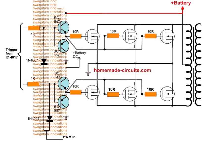
To get get a full wave or a full 220V RMS, please replace the half bridge circuit with a full bridge driver IC circuit

Questions & Answers
Sir ineed an alternative ckt for h bridge invertor . So icant fint the above ic in the my area .
There is any alternative solution for make full bridge invertor with out the abaove ic
Naseef, you can try the following circuit
https://www.homemade-circuits.com/simplest-power-inverter-circuit-using/
Sir
The above ckt using 555 cannot give 150v DC input .
Ineed to get output 110v ac when input is 150 v
Swagatam hi, my question is sort of off topic sorry about that. I'm trying to use, my old 600watt ups as an inverter using Li ion 18650 batteries (3s 16p). I use a bms to protect the batteries. My problem is that since the ups is designed to use deep cycle batteries it turns off at 11.4v while my bms cuts off at 9v. I can't use the full potential of the batteries. Any suggestions? What do I have to change in the ups to trick the ups and run till the bms cuts power to the ups? Thanks in advance Swagatam.
can i get this circuit board be prepared.. how much it costs
Hi Dilandki,
I don't think you can trick the UPS charger externally, the only way of solving this could be by bypassing the UPS charger and using only the BMS for charging the battery, or alternatively you can try identifying the low cut-off adjustment in the UPS board and set it to cut-off at 9V
Mr. Swagatam Majumdar
Please, i need some help. What values for RT, CT, LT and LR in diagram circuit?
I do not know much about electronics, so i need to know what the values of these components to carry out the project.
Can you help me, please.
Thank you.
Hello Amadeu,
Rt, Ct could be calculated through the formula presented in its datasheet, or you can find it by some trial and error also.
L is not compulsory you can replace it with a wire link….RL is your load which you would be connecting with the UPS
sir 7kw inverter digaram or 3hp/5hp ac sabmarsibal pump puc unit digaram send me.
or 5hp 3 phase motar driver direct solar
OK in that case you can try these two in a Darlington configuration and check the response….
But tip122 cannot use 300v like mje13003 that was why i asked rememba my circuit is Ac to Dc meaning 300vdc after rectification sugest d rite bjt 2use as a replacement 2d tip122
Ok. Can i use mje13003 in place of the tip122 and 2sc5296 in place of the tip35 in the circuit you suggested? I won't be paralleling just like u did in the circuit. Help!
mje13003 is entirely different from TIP122 so they cannot be interchanged,
2SC5296 might work in place of TIP35
I' m currently designing an 800w pushpull Ac-Dc smps using a 556 pwm to clock a CD4017 which i intend to use to drive 2 x 2sc5296(800v, 8A). But i don't know how to drive it into saturation from a CD4017 since the maximum current of the CD4017 @ 10v is 0.9mA(according to the datasheet). the minimum hFE of 2sc5296 is 4. the power supply of the CD4017 is 8v, 500mA. tell me the best bjt to use as its base drive; a pnp or npn? Also show me how to connect it, is it as a common emitter, Darlington or sziklai pair? Help me in detail!
you may refer to the following article for more info:
https://www.homemade-circuits.com/2014/10/upgrading-low-power-inverter-to-high.html