In this post I have explained how to make and replace existing bulb type brake lights in vehicles with high efficiency LED lamps.The idea was requested by Mr. Awan.
Technical Specifications
I would like to build a brake lamp project using 1 watt high power leds, consisting of 12-15 leds. the leds would light on dim parking lights and would light full on brake pedal press. kindly provide me a circuit.. kind regards, Awan
The Design
LEDs are a lot economical than ordinary incandescent lamps or even the modern halogen lamps in terms of their efficiency, luminance and life.
Therefore even in automotive field we can now witness a rapid transition from the old filament type bulbs to the modern high bright LED lamps.
These are normally being implemented as brake lights and head lights in most modern and the new generation vehicles.
In the proposed automotive brake light circuit 1 watt high efficiency LEDs are employed for executing the ultra high intensity illumination.
We all know that basically today's all modern high watt LEDs require two crucial parameters in order to function correctly and safely, namely a current controlled supply and thermal or heat controlled assembly.
The first criterion can be implemented by using any modern sophisticated linear IC such as a LM338, I have discussed it elaborately in one of my previous articles high watt LED current limiter circuit.
For the second condition one can simply use a special aluminum base PCB mounted on a heatsink for assembling the 1 watt LEDs.
Circuit Diagram
Circuit Operation
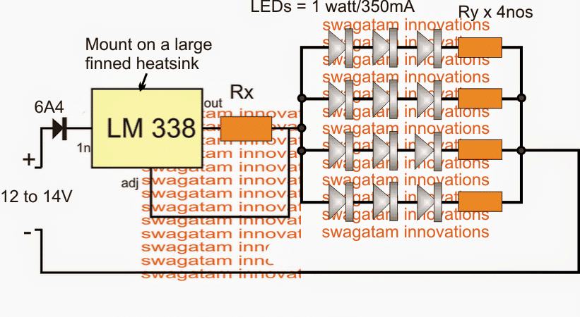
The circuit for the LED brake light may be witnessed above, and it looks pretty straightforward.
The LM338 is configured as a current limiter, where Rx determines the maximum allowable amps to the connected LEDs. It may be calculated using the following formula:
Rx = 1.25/LED current
When LeDs are connected in series there effective current consumption
is always equal to the rating of the one individual LED. Therefore in
the diagram each string would consume 350mA since this is the rating of
each 1 watt LED.
Combined current for all the three strings would be 3 x 350mA = 1050mA or approximately 1 amp
Substituting the above parameter in the formula we have:
Rx = 1.25/1 = 1.25 Ohms
Wattage = 1.25 x 1 = 1.25 watts
The resistors Ry which can be seen connected in series with the LEDs are actually optional, these may be included only for assisting the IC and providing proper balance across the LED strings.
It may be calculated using the following formula:
Ry = (Supply - LED total FWD voltage) / LED current
Since here the LEDs are specified with a forward voltage of 3.3V and 3 nos
are arranged in the series, the combined forward voltage becomes 3 x 3.3
= 9.9V
For reducing full loading of the LEDs, we can take the current at 300mA instead of the specified 350mA
Therefore Ry = (13 - 9.9) / 0.3 = 10.33 ohms or simply 10 Ohms
wattage = (13 - 9.9) x 0.3 = 0.93 watts or 1 watt
It seems we missed an important inclusion in the above diagram, it's the dimmed LED feature during the normal course of the vehicle and while the brakes are not applied.
The following diagram suggests how simply this may be implemented using a parallel connected resistor Rz, with Rx.
Applying the Dimming Control
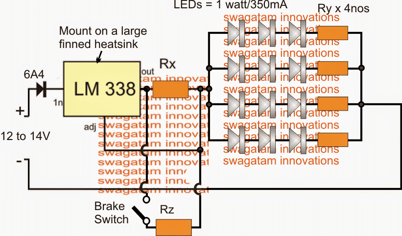
Here the values of the Rx and Rz may be identical but twice that of the above calculated value that is 1.25 x 2 = 2.5 Ohms. This would allow a 50% dimming of the tail lights while the brakes are in the released position.
If one desires to obtain further dimming of the LEDs Rx may be increased to 3 ohms or 3.5 Ohms, this would also mean lowering the Rz value proportionately such that the parallel value of the two resistors constitutes 1.25 Ohms.


Questions & Answers
Hello,
As I know nothing but the very (very!) basics about electronics could you help with designing a 50% power reduction circuit for LED auxiliary spotlights on a motorcycle, please? The ones I have are perfect as DRL but are much too powerful for night use. All I do is dazzle other drivers. I need to reduce the power for town riding and only use full power out in the country lanes.
I have a 3 position switch On-Off-On so I can choose between the reduced and full circuits. The lights are quoted at 40w each (x2) and 12V (13.8v across the battery when the bike is running)
I can follow the logic of your circuit, but can’t find any suitable components for what I calculate as 6.6amps. As I said — I know very little about electronics (for which read I know nothing :-))
Thank you in advance for your help – It is great to be learning new stuff.
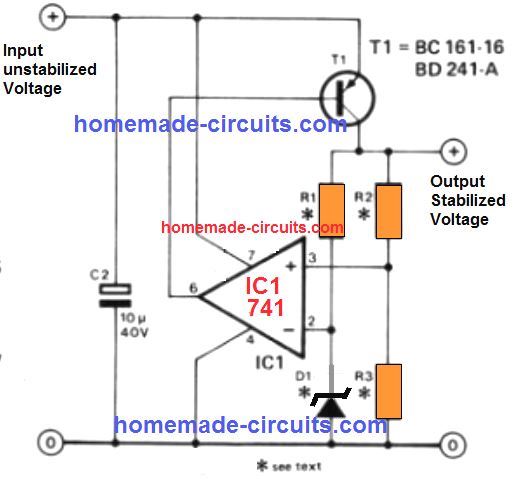
Hi, you can try the following PWM circuit for controlling the brightness of your DRLs:
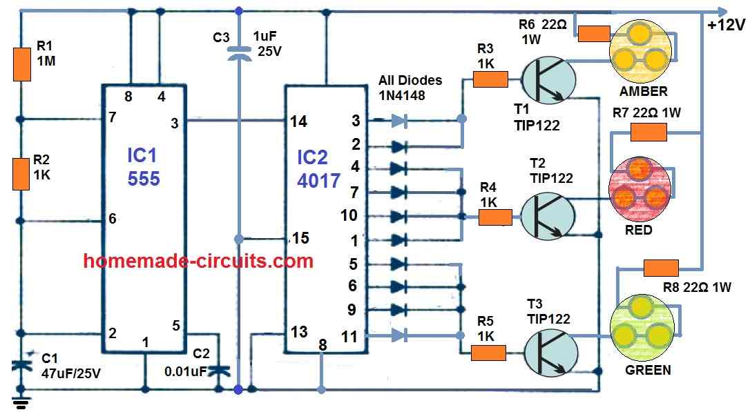
I have used a small changeover switch which selects between the 1k resistor points and connects to the capacitor, this switch can be as per your choice, it only has to fulfill the selector function across the indicated points. This switch can be also a 4 pole rotary switch which can provide a 4 way control of the brightness of the DRLs. Only two poles are shown which can be extended to 4 pole selection by adding the ends of the 1k resistors to the switch.
Hi Swagatam,
I happened to come across this site when working on my own led tail light conversion. Funny enough we arrived at nearly the same solution. Thanks for the clear explanation as it helped me to double check my design.
You can find my version at:
Cheers,
Maarten
Thanks!
Hi Swagatam,
I earlier asked about substituting LM317 for Lm338. I found the answer in another of your posts about current limiting circuits. So the 317 allows for 1.5 amp and the 338 allows for 5 amp. My other question is why do we need the 6 amp diode? Just trying to learn! Thanks!
Hi Norman, A diode’s current capacity should be at least 3 times more than the load, otherwise it may start heating up, that’s why I have used a 6 amp diode for the 1.5 amp load
Good day sir! May I ask for part list for this circuit? Having a 15 LEDS?
Micheal for 15 LEDs just repeat one more parallel string with the existing 4 LED strings. You can easily calculate the parts with the given formulas
sorry to bug you, can you please explain me this
Here the values of the Rx and Rz may be identical but twice that of the above calculated value that is 1.25 x 2 = 2.5 Ohms. This would allow a 50% dimming of the tail lights while the brakes are in the released position.
If one desires to obtain further dimming of the LEDs Rx may be increased to 3 ohms or 3.5 Ohms, this would also mean lowering the Rz value proportionately such that the parallel value of the two resistors constitutes 1.25 Ohms.
In the above comment I meant to say,
optimal brightness when brakes are applied….and 50% dimming when brakes are released…
for optimal brightness the Rx + Rz combination should be = 1.25 ohms, therefore since both are in parallel there effective resistance must be 2.5 ohms.
but this will allow only 50% dimming, for more dimming you can use the following formula and work out the values of the respective resistors:
1/R = 1/Rx + 1/Rz
that is 1/1.25 = 1/Rx + 1/Rz
if i use 13 or 14 leds, how would this work out then..
you can use either 12 or 15 LEDs… not 13 or 14.
12 is already shown, for 15 add one more string, and calculate Rx, Rz as explained in the article and the comments
What is 6A4 sir
it's a 6 ampere rated diode
thank you for the diagram and details, appreciate your passion for helping us world wide,
i will get back to you for any help or query.