In this article I have explained to make a simple 12v LED backpack power supply circuit for powering a 36watt LED lamp, which includes appropriately wired integrated sockets for enabling the attachment of external devices such as a regulated battery charger, ammeter, voltmeter etc. The idea was requested by Mr. Kevin Bates
Backpack LED Charger/Driver
Firstly, I must thank you for tasking the time to look at my project with me. Although I have some understanding of electrics and electronics I am not very knowledgeable . I am an engineer by trade and have a good head for visualization and comprehension; I am also skilled at machine works and soldering.
This project is a hand made wooden backpack with three equal sized compartments ; the bottom two have a single fixed cover held in place with brass wing nuts and the top cover is hinged : -
1. The bottom one; this will house the battery. It is vented via the brass louvered grill.
2. The middle compartment; this will house all the electrical , including those which face out (panel mount) through the outer cover , being the Isolator switch, charging socket, amp meter and volt meter.
3. The top compartment which has the hinge is for storage of daily bits and bobs. The concept: - In our Steampunk world, my wife is a time jumper and I , a demon catcher . I wear the backpack which has a special gun which fires a charged beam of particles (not for real) this interrupt the jumper and demons ability to teleport .
Once captured the demon or jumper is held in stasis. This is where the LED lights come in, representing the particle beam.
The LED controller has an infrared pickup, which controls the motion, color and speed of the lights. The feed to the lights splits into two as it leaves the controller.
One section of lights goes down to my gun and the second section of lights goes down to my belt where it forms a lasso. This section has a hook on the end which can be clipped to a collar my wife wears. This forms the “ Keeper ” in our story, preventing her from Jumping at will.
With the Infrared remote either of us can control the lights movement, color, speed etc. Although the lights are split they remain a total of 36W
The battery will be recharged when the backpack is off , the charger is a self - contained (wall wart) type which came with the battery 12V 6 amps, so the charging socket is only an interface between the outside and inside the battery compartment. No charging circuit is required.
What I would like to achieve : -
- A circuit board which will provide me with a stabilized voltage regulation of 12V 3 A via a 5 A switching rectifier? to reduce heat generation, and incorporating some form of circuit protection – Which I will need your expertise to determine .
- The ability to run the volt and amp meter via removable plugs
- To use the Isolation switch to isolate the battery from the rest of the system during charging.
- As an option I would like a couple spare 12v out sockets mounted on the board so that I can expand in the future. I hope this is adequate , if not I will try again, if you ca n bear with me
Kind regards
Kevin Bates
The Design
Wiring Schematic Details
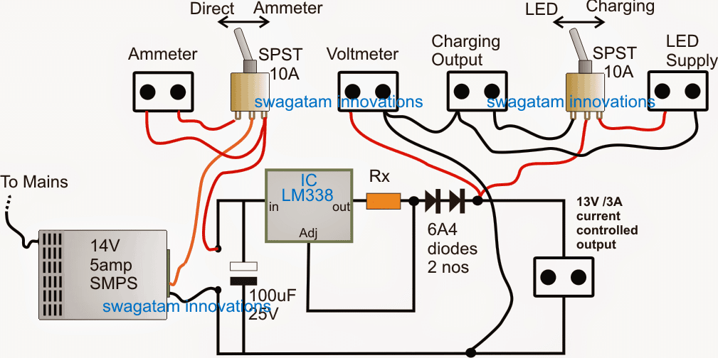
As shown in the above 12V LED backpack circuit diagram, the wiring and the circuit layout appears to be pretty straightforward, and with bare minimum components. The details may be understood as given under:
The input supply is acquired from a ready made 14V/5amp SMPS unit, which can be seen at the extreme left side of the image.
If the user prefers to build the SMPS himself he may do so by referring to the diagram that's presented in the following article
However procuring it ready made would be much easier and hassle free, and is recommended here.
As requested, the output from the SMPS can be seen passing through a changeover switch stage for enabling the option of a direct input to the load or through an ammeter depending upon the position of the SPST switch.
Next, the input supply is allowed to traverse through an LM338 IC stage configured as a current controller in order to manage the correct amount of amps to the load (LED modules), as well as for the charging of the battery.
The current limit is achieved by appropriately calculating the value of Rx. The entire procedure for calculating the current limiter resistor may be learned from the following article:
Universal current limiter circuit
As indicated in the request, the current controlled 14V supply is terminated into a couple of pluggable sockets, one for enabling voltage measurement externally, while the remaining two facilitate the powering of the LEDs and the charging of the battery via another SPST switch.
The regulated 12V output from this 12v LED backpack power supply circuit can be seen connected with an extra separate socket so that the user is able to access the voltage for powering any other desired 12V gadget through the same.
Design Flaws
Hello Swag,
Many thanks for your assistance, I took a look at your design but noted a number of things which I would like to put forward for your confirmation, please.
- I note a permanent charger SMPT....IN my design this would need to be the battery - I note a switch on Ampmeter, but I would need to have mine permanently connected. - You have labelled the Charging Socket as "Output" but I require it to be an "Input". My charger plugs directly into the wall and charging will be through this socket.
I have redrawn (in basic form) what you provided me but with my alterations, would you be kind enough to check the design through and make sure it is OK.
Many thanks and kind regards
Kevin
Using LM338 for Charging Battery and LED Control
Hello Kevin,
Thanks for pointing out the mistakes, however we have another associated problem here, it is the LM338 current controller circuit which needs to be used both ways, that is while charging the battery and also while illuminating the LED, therefore the wiring needs to be done rather in the manner shown in the attachment, please check it and let me know if you any doubts.
Hopefully this will solve all the indicated issues.
Best Regards. Swag
Circuit Diagram
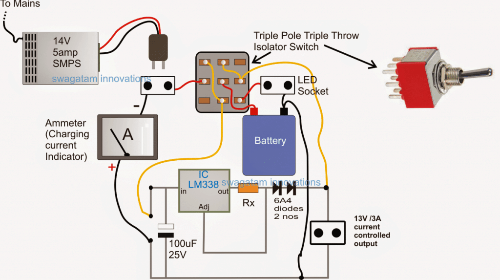
In the corrected diagram shown above, a single TPDT (3PDT) switch is employed and is able to achieve the intended charging of the battery as well as the illumination of the LED through a common LM338 current controller circuit.
So this idea enables both the charging of the battery and the illuminating of the LED to be implemented via a safely calculated current controlled supply, making the unit much compact and cost effective.
Rest of the section of the diagram are self evident.
Feedback from Mr. Kevin
Hi Swag,
Just to say thank you for all your help with this project, I have just ordered all the bits I need to complete.
All the best
Kevin

Questions & Answers
Hello dear Swagatam and thank you so much for your kindness and that you are such a good person. I will always remember you love and wish you the best.
yours truly
Roya
Thank you Roya, you are most welcome!
Hello dear Swagatam
I hope that you are healthy. I have a 220 to 18 Volts transformer and I know that the maximum input voltage of the following mentioned ICs is 25 volts. I would be very glad and thankful if you please tell me that if it would be possible for me to mount 5 Nos. of metal case regulated ICs ( 15, 12, 9, 6, and 5 V ) on a big single heat sink? won’t they burn? I am to connect each of the mentioned ICs separately to the 18 V output of the transformer.
Thank you in advance for your reply
Best regards
Roya
Hello Roya,
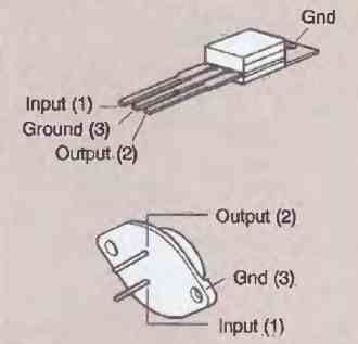
as far as I know, the the metal tab of the 3 pin regulator ICs are internally connected to the center ground pin of the IC. Therefore it means that the ground pins of all the ICs are connected to their respective metal tabs….since the ground pins are supposed to be the common line, therefore according to me all the ICs can be clamped over a common heatsink.
Hello, I’m working on a project and request some assistance. I make custom lamps as a hobby (all 110v) and a friend mine ask me to make a battery operated one in a cigar box. I would like it to power a 12v 6w LED E26 bulb and have 1x usb port to charge a cell phone. I would like for it to have the ability to plug it in to a 110v outlet to charge. It would be great to be able to have the light remain on and charge the cell while charging. I’ve looked into 12v rechargeable batteries but I’m not certain on the wiring. Would the diagram above work for me? Any assistance would be greatly appreciated.
Yes, the above diagram (2nd one) would work for your application!
The the USB port you will have use a buck converter for stepping down the 12V input to 5V, which can be procured as a a ready made module. Or alternatively, you can simply include a mobile charger module and connect it with the 110V input to get the 5V charger output
Thank you.
Hi Swag,
Please help me on this, i would like to change all my house lights to LED lights running by 12 100AH lead acid battery. for this i have purchase lot LED strip. each led stipe has 144 LED’s and it is 12V 20W. this is the light strip
now my problem is if i connect one led strip to the 12v 100AH battery led are too bright and getting too hot. if i connect around 20 LED strip one time then brightness ok and little hot too. i thing the battery Ampler is too high for this led strip. ( i have try with 12v 4.5ah battery its perfectly fit)
so i wish to assemble a circuit, it can control or reduce the ampere according to the light.
if i switch on one light or all, circuit has to give limited voltage/ampere to each light.
or each light strip i want to add a small circuit like this.
i think you may know what kind of circuit aim looking for. if you know any such circuit kindly give me a reply.
Regards.
Hi Mohamed, if the voltage is maintained at the specified 12V then current can never have any effect. Whether is 12V/100Ah or 12V/4.5Ah both should have the same heating effect.
Your strip may be getting warm because the 100Ah is able to sustain the required full 1amp without dropping 12V, whereas your smaller battery could be dropping voltage in an effort to compensate 1 amp, and that’s why the LED may not be getting warm due to reduction in overall power.
However the LED strip already has limiting resistors and is not supposed to get hot at the specified 12V, at any circumstances?
Anyway if you are looking for a current control system, you can employ the following concepts:
https://www.homemade-circuits.com/universal-high-watt-led-current-limiter/