In this post I have explained how to build and use a 18V battery charger circuit for a cordless drill machine. The idea was requested by Mr. Chibuzo.
Technical Specifications
- Here is the issue. I don't have any cordless drill battery charger at all. But I have variable voltage car battery charger.
- I did try to use it by sticking metal plates on the terminal of the battery pack but I found out that the battery pack became warm /hot after a while, so I quickly disconnected it.
- The battery is 18V nicd and I fear if it is not already dead/roasted I might destroy it by pushing in too much current at once using the car battery charger.
- I know you are a very good subject matter expert in this regard, am looking forward to you suggestion. Like I said earlier, am a hobbyist with interest in many areas and I use these tools but getting them charged is an issue for me so am looking for a permanent solution.
- Finally am going to try my hands on as many of your projects I can possibly find parts to handle. Can I personally get across to you if I have problem as I make effort to improve my knowledge of electronics using your platform. Am willing to be your student.
- Thanks for such a large heart as to be willing to share what you know with total strangers. Again, am very sorry to trouble you.
The Design
Whether it's a lead acid battery, a Ni-Cd or a Li-ion, this multipurpose battery charger shown below can be applied for any of these for charging them efficiently and without worries:
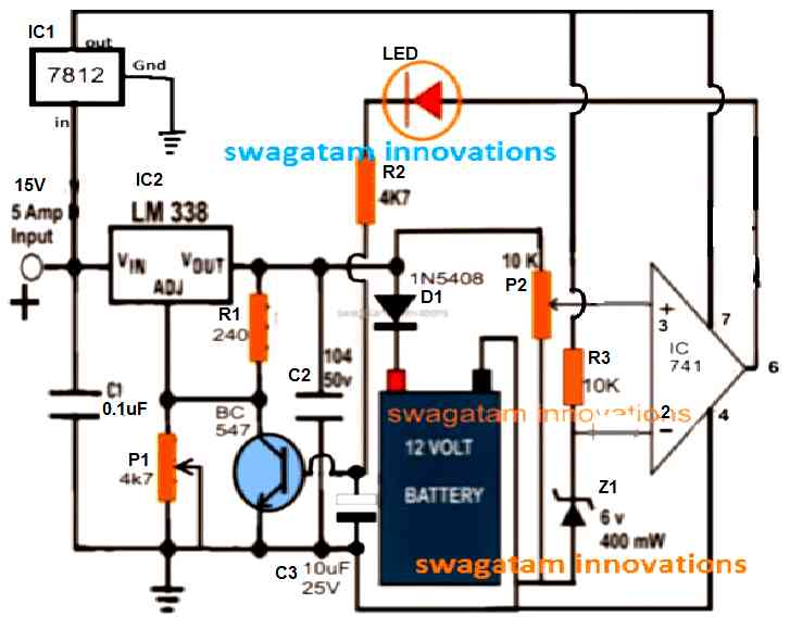
The salient features of this universal automatic battery charger are:
1) Constant voltage charging
2) Automatic cut-off when battery is fully charged.
3) Max current 5 amps, which means batteries up to 50AH can be charged with this charger normally.
4) Fully customizable as per the battery specs.
5) Low cost
6) No special parts required, all are standard and easily available.
7) LED indicators for cut-off and charging status monitoring.
8) Suitable for garages and home use.
How to set up this simple cordless drill battery charger circuit:
The entire procedure has been comprehensively discussed in this post which explains how to set or adjust an opamp 741 IC based battery charger circuit for implementing an automatic cut-off
The above universal charger circuit is a constant voltage charger and a constant charger when it's implemented as a 5 amp charger, however for lower current charging this circuit might require an additional charging LM338 constant current circuit between the input supply and the above circuit.
Step by Step Setting Up Procedure
- Initially keep the base/emitter of the BC547 shorted.
- Rotate the P2 preset wiper to ground level.
- Without any battery connected, switch ON the input power, and adjust the P1 preset until you get 14.2 V between the cathode of D1 and the ground line.
- Next, adjust the P2 preset, until the LED just illuminates.
- That's all, the setting up procedure is complete.
- Finally, remove the base/emitter short, your cordless battery charger circuit is now ready for the automatic charging and cut off..
How to Charge a 18V cordless drill battery with the shown universal charger circuit
Cordless drill battery can be mostly a Ni-Cd battery which is not as critical as the lead battery counterparts as far as the charging parameters are concerned.
Quite like the Li-ion batts these too will allow you to charge then through a current which may be 1/10th of their AH rating or as high as their specified AH rating.
For example if the drill battery is rated at 3AH, it could be charged at 3/10 = 0.3 amp or 300mA current rate, or any current within 3 amp but not exceeding this limit.
However at the full 1C charging rate the battery could get significantly warm, which must be taken care by an automatic temperature controller circuit or through fan cooling.
PCB Design for the above explained Cordless drill battery charger circuit

Track side view
Parts List
- Resistors
- All resistors are ¼ watt 5%
- 10K = 1no
- 1K = 1no
- 240 ohms = 1no
- 4k7 or 4.7K = 1no
- 10K preset = 1no at pin#3 of IC 741
- 10K pot = 1no connected with ADJ pin of IC LM338
- Capacitors
- 10uF/25V = 1no
- 0.1uF/50V = 2nos
- Semiconductors
- BC547 = 1no
- IC LM338= 1no
- IC7812 = 1no
- IC 741 or any similar opamp = 1no
- 1N4148 diode = 1no
- 1N5408 diode = 1no
- 6V and 3.3V Zener diodes = 1no each both can be ½ watt rated (can be replaced with 4.7V Zener for both)
How to Build
Power Supply Stage
Make use of a 15V DC source that can provide the LM338 regulator with at least 5A.
Connect the input of the 7812 regulator IC to the 15V supply after soldering it on the PCB. The op-amp and control stages will get a steady 12V from its output.
To make sure the 7812 and LM338 can manage heat dissipation efficiently add a heatsink to each.
Voltage Regulator LM338
In accordance with the circuit schematic, solder the LM338. To modify the charging voltage, use P1 (a 4.7k potentiometer) and R1 (a 240 ohm fixed resistor).
For stabilization of the regulator, solder a 10uF/25V capacitor (C2) at the output and a 0.1uF capacitor (C1) at the input.
For adjusting the output voltage to 19.5V to 20V which is a little higher than the battery voltage, customize P1.
Connection of the Battery
Connect the batterys positive terminal using D1 (1N5408). The reverse current flow from the battery to the charger is stopped by this diode.
Make sure the negative terminal of the battery is firmly attached to the circuit ground.
Circuit for Op-Amp
The 741 IC should be placed on the PCB. To establish the cutoff voltage solder the P2 (10k potentiometer) and R3 (10k resistor) to the voltage divider.
To set the battery's cutoff voltage at about 20V, customize P2.
The transistor (BC547) and LED for charging status indication should be controlled by the op-amp output.
LED indicator
Mount and solder the LED to the BC547's collector using a series resistor (R2, 4.7k). As soon as the battery is completely charged, this LED is going to turn off to show the cutoff state.
Reference to Zener
Mount and solder a 400mW, 6V zener diode (Z1) to give the op-amp a steady reference voltage.
Calibration and Testing
Once the circuit is put together, use a multimeter to check the LM338's output voltage.
P1 and P2 may be gradually adjusted to establish the charging voltage and optimize the cutoff point, respectively.
Before attaching the battery make sure the circuit is working properly by first connecting a fake load, such as a 12V lightbulb.
Calculations
LM338 Output Voltage:
Vout = 1.25 * (1 + R1 / R2) + Iadj * R2R1 = 240 ohms (a fixed resistor).
R2 is adjusted via P1 (4.7k potentiometer).
Iadj is typically very small and so can be neglected for simplicity.
Approximation:
Vout ≈ 1.25 * (1 + 240 / P1_adjusted)Zener Reference Voltage:
Vref = Z1Z1 is the zener voltage (here, 6V).
Cutoff Voltage:
Vcutoff = Vref * (1 + R3 / P2)Vref is set by the zener diode.
Adjust the P2 to set the desired cutoff voltage (e.g., 20V).
Charging Current:
Icharge = (Vout - Vbattery) / RlimitingRlimiting is the resistor in series with the battery (if its used) to limit the current.

Questions & Answers
Mr.Swagatam,
Good day sir how are you keeping and it ha been a few months since I last received such valuable battery charging information fom you I appreciate that to this day but, I need to charge my video camera lithium battery which is about 14.4V and it is a lithium ion battery.
In fact I have three but need to charge them PLEASE, provide me with a circuit I am desperate as my charger fir these batteries haveg one “dead” in other words it does not charge so well anymore.
Once again Sir, please provide me the link where I may find a suitable charger even if the output voltage is a little higher than 14.4V in order to charge my batteries.
I think once apon a time you had a circuit for a 22v lithium charger not sure though but please do you best and advise me at your earliest convenience thank you in advance.
Kind regards,
Dr.Christopher (Chris) Halgryn (Ex Swedish citizen)
Auckland.
New Zealand
Sir,
At last it is weekend time and I appreciate your welcome email meesage with gratitude.
I have started the pcb and list of components and soon I will manufacturing the PCB and then populate the board.
It is indeed a pleasure to receive such valuable electronic advice and everybody else should express their thanks too….to you Sir for your prompt replies and valuable information how to construct and test, thank you for all that information on my and all the other enthusiasts behalf….thank you.
Respectfully,
Dr.Christopher (Chris) Halgryn
Auckland
New Zealand
You are most welcome Dr. Christopher,
I wish you all the best with the project. If you have any issues with the working of the circuit, please let me know, I will try to solve it ASAP…
Thank You Dr. Christopher, it is a pleasure to have such a dedicated reader like you in this website.
For charging your Li-ion battery, you can use the same circuit which is explained in the above article.
If you want to have a permanent cut off at the full charge level, you can simply replace the BC547 transistor with an SCR.
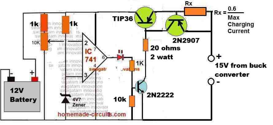
Alternatively, you can also try the following design which is even simpler, yet is fully equipped with a constant current and an automatic cut off features. Please let me know if you have any further doubts regarding these circuits:
How about designing a battery charger utilizing a solar panel? These panels produce DC.
Good day, relating to the above circuit, the diagram shows a 6V Zener. But in the Parts List, a combination of two Zener diodes are listed. The combination in series would amount to a about 10V [6 + 3,3 or 4.7 + 4.7], is this to set the opamp switch voltage? And can you please indicate how this will affect the operation of the circuit as shown in the schematic. Thank you.
Hello, Thank you for your question,
Actually the second zener diode expressed as 3.3 V was supposed to be in series with the base of the BC547 transistor.
But since we already have an LED in series with the base so this specific zener diode can be eliminated.
So please ignore the 3.3V zener, only the 6V zener is relevant which can be replaced with a 4.7V zener diode also.
Thank you for your help
How do Iobtain a kit to enable me to build the 18 volt battery charger or can I purchase a feast made board?
I am sorry, the components cannot be procured from this site, you may have to buy it from an online part dealer.
If you have any problems building the circuit, please let me know!
Hi. Will this charge a 70ah or 100ah lead acid battery
Hi, you can put another LM338 in parallel and then use the design to charge a 70 Ah battery
Thank you for the very fast and prompt reply and to you Sir and your family, may you have a Prosperous new year 2023 soon.
Thank you again.
Dr.Chris.
You are welcome Dr.Chris.
Wish you and your family too a Happy and a Prosperous new year 2023
Sir,
Dr.Chris here again please advise me if the above lithium charger pack will charge my VIDEO CAMERA 16v lithium battery pack.
Also, can you add to the circuit a protection to avoid overcharging the battery pack perhaps??? thank you kindly and, thank you for the last reply all works so well as far as my project using your circuit works exceptionally good!!!! thanks to you again.
Thank you so much Dr.Chris,
I am glad my circuits are working properly for you.
yes you can use the above battery charger circuit for charging your 16V Li-Ion battery.
The circuit already has an over-charge cut off feature, so nothing to worry at all. Just make sure to adjust the cut-off threshold correctly.
Hello sir.., I want to charher my mexmech battery 24v lithium battery but I don’t have a charger. My original charger is not working .sir can I build charger.
Please sir advise me
Thank you
Hi Peace, you can definitely build the charger using ordinary components like LM338 IC, bridge rectifier, transformer etc.
Please HELP I want to charge my 18v lithium battery for my drilling machine but I do NOT have a charger my original charger is not wo9rking anymore . Can I build a charger BUT Sir, there are three terminals in the original charger what is the third connection for and is that connection necessary. PLEASE advise at your earliest convenience.
Thank you
Dr.Christian Swinton
Sir,
Thank you gosh this is the fastest response I have ever received from anyone sometimes different questions but your fast response is greatly appreciated…. thank you again.
The schematic indicates a “sealed lead acid “battery am I wrong and is that circuit you showed me for lithium batteries as well also, the damaged charger I used before to charge my 18v drilling machine well….the charger had THREE TERMINALS yet your charger shows two wires only please advise, what actually is the third connection for on the charg for and I say Thank you in advance . Dr.Christian…………
You are welcome Dr.Christian,
Yes the diagram shows a lead acid battery, but the same charger can be used for Li-ion battery also simply because we are not trying to charge the battery fast. As long as the battery is not charged at a fast rate, this charger can be universally used for all types of batteries. The charging current indicated in the formula must be around 50% of the Ah rating of the battery.
Regarding the 3 pin in your charger, I am actually not sure about it. All batteries have two terminals only and require just two terminals for supplying the charging voltage. Likewise you can use just two charger for charging battery too, without any issues.
Hello Christian, you can simply build the following circuit and use it for charging your 18V Li-ion battery. However make sure to adjust the pot so that the output voltage is set slightly lower than the full charge level of the battery. For example if 18V is the full charge level, then set the output to around 17.9V or 17.8V.
hi swagatam.i like the 12 volt circuit for its cimplicity but i need a circuit to charge 5 cell li ion batteries in series thus mean 20 volt across them. can this circuit do the job?and if so how to adjust the 10k pot on pin3 of 741?my best regards.
Hi Nikos, yes that’s possible. For this you will have to adjust the 4k7 preset to get 20V at the output of LM338, and then adjust the 10k preset at a point where the LED just illuminates.
While setting up the 10k preset make sure to keep the BC547 collector disconnected from the ADJ pin of LM338, and also keep the 1N4148/1k link disconnected.
Connect them back once the setting up is complete.
hi.
i made a circuit like this, it works very well.
What exactly does feedback do?
When I removed this pin, the circuit worked fine.
thank you for everything
Hi, the 1N4148/1k feedback is introduced to latch the op amp output to high position and permanently switch off the IC LM338, until the input power is switched ON and OFF.
If you don’t put the feedback, when the battery is fully charged, the op amp output will switch ON, and disable the LM338 output cutting off power to the battery. Now, due to lack of charging voltage, within seconds the battery voltage will try to drop slightly below the full charge voltage level. This will prompt the IC output to switch OFF and the LM338 will again resume charging the battery. This rapid ON/OFf will go on at the full full charge threshold, if the feedback is not used
Good I am interested in this circuit because the charger of my drill burned and it is 18v, my query is in the diagram that you can see a 0.1uf capacitor between IN of the lm338 and connected to ground which cannot be seen in the PCB design also the other one that is 104 / 50v that is connected between ground and to the output of the lm338 which is the reason, finally I already placed all the components in their place but the preset connected one to pin 3 and the other to ground of the 741 it seems to me that it is a trimpot and the other terminal is on the air that says IN on the pcb what is the function of this terminal please thank you very much
The capacitors at the input and output of the IC LM338 are completely optional, since the input supply would be near to the IC. The capacitors are required only when the source input supply is some distance away from the IC.
The center pin of the P2 preset is connected to pin#3 of the IC, one of the other terminals is connected to ground and the 3rd terminal is connected to the body of the LM338 which is the output of the LM338. The LM338 body connection pads are shown as large round copper pads.
I have updated the diagram, and have removed the diode and resistor which were connected across pin#6 and pin#3, because these were not important.
hi.. im francis from the philippines, my question is this 18v charger is also good for 220v input?
Hi, You will need a 220V to 18 V DC adapter to feed the input of the circuit, and for charging the battery from mains
I have answered my own question. In looking up parts at jameco.com there is no listing for a 4k7 or 4,7k pot
In the schematic it shows a 4k7 pot connected to the ADJ on of the lm338. In the parts list it calls for a 10k pot to be connected to the ADJ pin of the lm338. Which is the correct pot to use?
Great design. I have several power tools with 18 volt nicad batters. The charger was lost during a recent move. Will be good to have use of then again.
Both will work! Higher values will cause higher portions of the pot’s dial calibration to become unresponsive and wasted. For 4k7 this may be 20% wasted and 80% working, for 10K this may be more than 50% wasted, and so on.
Glad you liked it, hope the design does the job for you.
Thank you.
John
Sir, are printed circuit boards available to purchase either from you or commercially if so how can I purchase one.
Throston,
Thank you
Sorry John, Ready PCBs are not available from me at this moment!
Hi Swagatam,
On your circuit diagram you use a 7812 voltage regulator, this is a 12 V regulator, is that correct for an 18V charger?
Can I / should I use something like ST L7818CV instead?
The battery I need to charge is only 1.5Ah, would charging it at 0.3A be ok and do-able with this circuit?
Great site by the way.
Cheers
Phill
Thanks Phill, the 7812 is for supplying 12V to the IC 741, it’s not for the battery. Because a 741 won’t tolerate over 18V. The input should be around 21/22V for charging a 18V battery. 0.3 A will be fine for a 1.5 Ah battery, just make sure the battery does not get warm during charging, otherwise you may have reduce the current.
Makes sense, silly me!
Thanks for prompt reply!
I’m bookmarking this place 🙂
My pleasure Phill, thanks for Bookmarking, appreciate it!
Sir Its working well. But LM338 too hot and burned. For a 14.4 battery, can I use 17volt DC instead of 24 volt? I don’t need to adjust the out put so can I remove the LM338 ?
Glad it’s working Ajit. An LM338 IC will require a heatsink for proper functioning, but under no circumstances it can burn because it has in-built over heat shut down.
Anyway if you don’t want to include the IC it’s fine, but you cannot connect 17V to a 12V battery directly, you will have to employ an auto cut off system such as this:
https://www.homemade-circuits.com/usb-automatic-li-ion-battery-charger/
Hi Mr Swagatam, God bles u for helping people. My observation is that some of the parts are not Labelled for identification. Pls,for we who ar not experts, kindly make sure to label them for identification. Am Yusuf
Thank you Yusuf, I’ll try to update the parts list soon for your convenience!
Dear Sir,
Sir can i use this circuit to charge 4S li-ion 18650 battery?
I have a 4S 18650 battery pack that my friend gave me for use with my cordless drill., or do i need to a balance charger for this?
Can you please give me some advise
Thank you very much sir..
Dear Paul, ideally you should use a balance charger, but on temporary basis you can use this charge\, it will do the job reasonably well just make…
Thank you for the reply sir..
Do you have a simple balance charger circuit sir for my 4S battery pack? Can you provide me a link for it..
Thanks a lot..
Paul
Paul, you can try this concept, but please try it only after understanding the concept thoroughly…
https://www.homemade-circuits.com/lipo-battery-balance-charger-circuit/