In this article I have explained a simple remote controlled submersible pump circuit which could be simply configured using any standard 2 channel 433MHz remote control modules.
The idea was requested by Mr. James Smith
Circuit Objectives and Requirements
- I have read a lot of your post and have successfully implemented them several times.
- Now I want a design for switching my submersible single phase motor on and off via remote control.
- On the starter there a push button for on and push button for off.
- The push button is pushed only for 2 seconds and released and the motor is ON.
- The same for stop. The push button is pushed for 2 seconds and the motor is OFF.
- Pls help me in doing this as we are having trouble going up and down the staircase from 7 floor to ground floor to just ON and OFF the submersible motor.
- If the circuit is ready, I will just connect it to the push buttons.
The Design
We have already witnessed the basic triggering concept of a submersible pump using an automatic "start" and "stop" implementation of the pump contactor switches.
In this remote controlled submersible pump circuit also we follow a similar concept but instead of water sensors, here we do it using a remote controlled modules and subsequent momentary relays switching for initiating the relevant start stop buttons.
For this we can employ a two channel 433 MHz RF remote control modules, which are extremely accurate with their working.
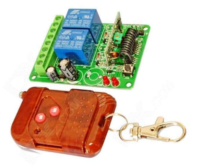
I would recommend buying this unit instead of building one, because these are quite cheap and are easily accessible through online electronic stores.
However if you are interested to make it, you could try it out by procuring the recommended chips for these remote controlled modules which are also available through all standard online electronic retailer.
If you purchase the units readymade, then it's just about configuring the relay contacts with the submersible start, and stop buttons, as shown below.
To be precise, it's the N/O and the pole of the relays which needs to be connected across the submersible buttons.
For identifying the relay contacts of the remote receiver unit one may take the help of one my earlier pasts which explained how to understand and use relays in circuits.
However since the contactor start stop buttons could be specified to work with high switching current, these may require special high current relay driver stages for the individual buttons.
Therefore the triggering supply from the remote receiver relays needs to be further integrated with the above mentioned high power relay driver stages as demonstrated in the following figure:
Circuit Diagram
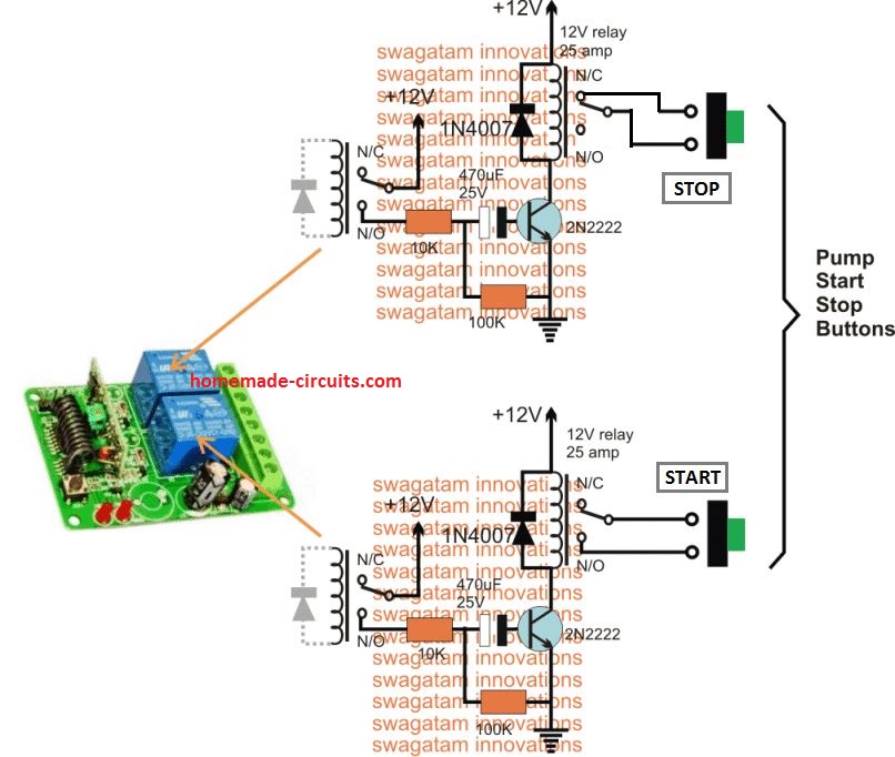
The relay driver stages shown at the right side of the diagram is made by configuring transistor relay drivers with the respective high power relays.
The bases of the transistors can be seen connected with series high value capacitors, this is to ensure that the relays remain activated only for a couple of seconds, regardless of the switching periods of the remote control module's relays, or regardless of how long the user keeps the remote transmitter handset button pressed.
The shown remote control receiver module consisting of the receiver circuitry and the two relays will need 12V supply from an appropriate DC source, such as a 12V AC DC adapter.
This 12V further needs to be configured with the relay contacts and the relay driver stages also, for enabling the intended remote controlled start/stop switching of the submersible ON/OFF buttons.
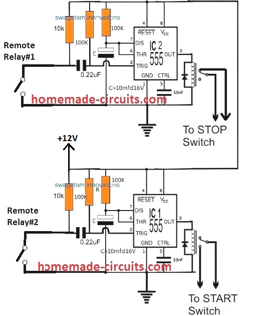
Using IC 555 Monostables
The above explained remote controlled submersible start stop operations can be implemented even more accurately by using IC 555 monostable circuits, as shown below:


Questions & Answers
Is submersible Pump control by mobile app possible?
Not through mobile app, through RF remote remote control as explained above.
Hi sir,
I want to make a remote control for motor to control it wirelessly. It is easy with 433 MHz RF Tx and Rx module. But I want a notification in remote using light or buzzer for 1. when the motor is running on Low Voltage, 2. when the motor is dry run etc. Fot this I think that there should be Tx with motor and Rx in Remote for giving such notification. If I use two 433MHz Tx and Rx module will it work or interupt with signals. Is there any module which work as Tx and Rx both.
Hi Rakesh, you will need an Arduino circuit for that….you can refer to the following page for getting those designs:
https://www.homemade-circuits.com/?s=GSM+pump
Hi sir,
Is this possible without arduino?
I want to know that how can i make tuned remote control system like car remote key.
Hi Rakesh, I think it is possible to build the messaging indication system without Arduino, but for that you will need two pairs of 433MHz Tx, Rx units for accomplishing the results.
Sir, humko 3 phase submersible motor ko remote control banana hay …
Sir, I am very poor man…
So, plz help me…
Aapka WhatsApp number do
Dhaval, building the remote can be difficult for you unless you are an expert with electronic circuits, I would recommend you to buy a "single channel RF remote control module" and then wire the relay contacts with a 3 pole contactor for controlling the pump.
Hi thank you for the help, can you let me know where i can purchase this device. if possible a link is better.
Hi, you can purchase it from any reputed online store, please search for "2-channel 433MHz remote control module" you will be able to find many suppliers online competing with the best prices.