In this post I have explained a simple electronic door circuit for pets which can be used as an electronic dog door for allowing only your specific pet dog to use the entrance, while keeping it locked for "strangers". The idea was requested by Mr. Dave Monette.
Circuit Objectives
- It's been a while since we talked. I just wanted to let you know the wireless 12v battery PIR long distance home security alert system we put up at my friends rural property is working great.
- We are able to now know if someone crosses the main bridge that approaches his driveway. We are getting almost no false triggers and the RF system is sending perfect signals at a range of over 1150 yards (over 1km).
- I have a new "pet" project (excuse the pun please).
- My girlfriend has two dogs and they use a doggie door on the back of her house to get in and out.
- However, since it doesn't lock she has come home twice to find the neighbor's dog in her house (he dug under the fence into her yard and then ran in the unlocked doggie door.
- I can install a new doggie door to replace the old one there, but I want it to be able to lock and unlock as the dogs get near it. Unfortunately, we cannot afford the $250+ USD the electronic ones cost.
- The ones available have a small pendant or tag the dog wears on his/her collar and the door will only unlock when the pendant is near the door.
- I sure hope that you can help us to design a locking door system.
The Design
The proposed electronic dog door circuit or electronic door circuit for pets can be easily built using a simple electromechanical lock set-up and a homemade Rf transmitter, receiver circuits.
The preferred door specification for this project should be such that it does not require a complex opening or closing operations. For example a sideways opening door or a sliding type of door could be quite complex to configure. Instead, a vertically hanging type of door (hinged at the upper edge) would be much easier to tackle and equip with the required electronics.
The basic electro-mechanical configuration for the door could be done as indicated in the following diagram
Mechanical Details of the Door
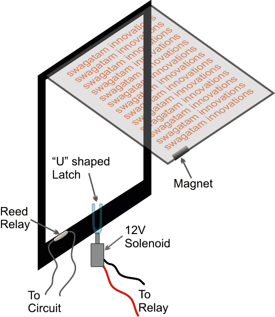
The door mechanism and the associated electrical can be understood with the following points:
The frame of the door consists of a central "U" shaped latch driven by a 12V solenoid unit.
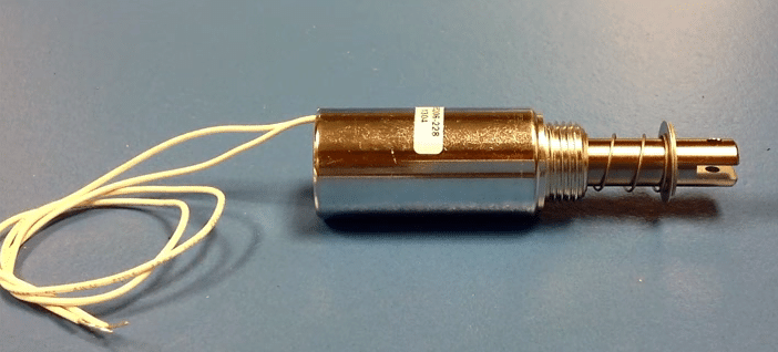
The Door Solenoid
The frame can be also seen having a concealed reed relay switch
The movable door lower edge is embedded with a permanent magnet such that while it's in its normal closed condition, the magnet aligns itself exactly face to face with the reed relay.
This concludes the door mechanism electrical, now let's see how this needs to be configured with an electronic circuit for the desired automatic "pet" triggered operation.
The Circuit Diagram

The circuit shown above is a simple delay ON timer circuit using T1, T2, R2, C2 as the main components.
Normally the delay timer is supposed to operate the relay after some delay as soon as the circuit is powered with an input supply of 12V.
However in the shown circuit design, the specified delay operation is controlled by two parameters, 1) the reed switch, and the opto coupler IC (with the attached BC547 transistor).
How the Delay Timer is Activated with Reed Switch
The reed switch and the corresponding magnet on the door ensure that the delay timer is activated only while the door is perfectly at the center of the door frame and is stable. In this position the delay timer is enabled by the reed conduction, which eventually operates the relay after the set delay has elapsed.
When the relay operates, it connects with its N/O contacts switching OFF power to the solenoid and causing the "U" latch to be pushed up for the intended locking of the dog door.
The second device which influences the delay timer and door locking is the opto coupler feed.
The optocoupler is triggered by an audio signal from an FM radio, which in turn is triggered by an FM signal from an FM transmitter circuit tied around the pet's neck.
Here we have selected a homemade FM radio, and an FM transmitter for the required signalling because the other forms of professional RF Tx/Rx modules could have high range which might be not be suitable for the proposed application, because we want the receiver circuit to activate only when the pet is much closer to the door and not while it's some 50 or 100 meters away, that would be simply spoil the purpose of the design.
How to Install the Transmitter Circuit
The transmitter circuit is supposed to be fixed on the neck-belt of the dog, and the FM radio needs to be installed with the door mechanism.
Once this is done, whenever the dog comes near the door, the FM radio detects the FM signal from the FM transmitter installed on the dog's neck and converts it into an amplified audio signal.
This audio signal activates the opto coupler which instantly disables the T1/T2 conduction, causing the relay to deactivate ( at N/C). With the relay contacts at the N/C, the door solenoid is immediately powered, and activated.
The solenoid now pulls the "U" latch down, releasing the door free to be opened by the dog through a quick head push.
Once the dog has entered and crossed the door, the door "tries" to restore its position at the center and after a few oscillations settles at its normal central position aligning its magnet with the reed switch.
The reed switch now enables the delay timer to begin counting, but this operation may be still inhibited unless the dog is completely out of the range, causing the opto coupler to shut off.
When both the criteria are fulfilled, the delay timer begins its counting and after the set delay "shoots" the "U" latch upwards locking the electronic door for all other creatures except the dog itself.
The dog transmitter circuit for the proposed electronic door circuit for pets or electronic door for dog will require a 3V button cell and can be built with the help of the following circuit.
Small FM Radio Circuit
![]()
Using a Two Transistor Small FM Radio Receiver
The receiver could be any standard small FM radio, tuned to receive the pulses from the above transmitter, and wired with the dog door assembly as explained in the above discussion.
The explained electronic door circuit is actually too simple to fabricate and install, and could be done even by new hobbyists who are well versed with the basics of the trade.


Questions & Answers
Sir I m huge fan of your work.. Again I need ur help.. I will be glad if you can help me… I m having some difficulties in interfacing arduino with RF434…
Thank Ujjwal, please provide and details and post the question under a related article, the above article has a different topic so I cannot explain it here.