This circuit will allow the user to lock his car ignition using his phone Bluetooth, meaning the ignition can be locked/unlocked only through a specific code from the user's cellphone Bluetooth.
Overview
In one of my earlier posts I have already explained how to hack a Bluetooth headset and use it for any desired switching application via Bluetooth, here we apply the same concept for the proposed car ignition lock circuit using Bluetooth.In the project the cellphone becomes the Transmitter circuit, and the Bluetooth headset is used as the receiver.
If you do not wish to modify the Bluetooth headset into a receiver circuit, you an procure a readymade Bluetooth receiver unit also for the same
The idea is actually very simple, and may be understood by referring to the below given circuit:
How it Works
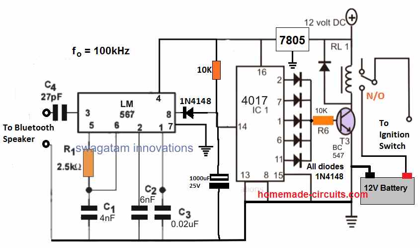
As can be seen the circuit is configured around a specialized phase-locked-loop IC LM567 which is designed to generate a low logic whenever it detects a frequency at its pin#3 that may be matching exactly to the IC's internal oscillator frequency set by R1/C1.
For example, in the above diagram the internal oscillator frequency is set at 100kHz by appropriately selecting the values of the R1/C1 timing components, therefore it implies that the IC will produce a low logic whenever it detects a 100kHz across its pin#3 and ground. As long as this situation is not satisfied, pin#8 can be expected to be at a logic high level.
The C4 end and the negative wire of the circuit is supposed to be joined with the Bluetooth headset or any selected similar Bluetooth audio receiver gadget. This could be also easily done through an opto coupler for allowing a complete isolation between the two stages.
This takes care of the Bluetooth receiver stage circuit, now lets' move on and learn how your cellphone needs to be set up as the Bluetooth transmitter unit.
For this, you will need to download a frequency signal generator app in your android phone, or if your phone is not an android phone, you can record a 5 second clip of the selected frequency, let's say a 100kHz frequency clip for the above shown design.
How to Test the Circuit
Once this is done, it's time to test the proposed Bluetooth car ignition lock circuit, through the following steps:
1) Pair up the phone and the Bluetooth receiver gadget with Bluetooth.
2) Toggle the 100kHz frequency from your phone and simply send it to thee receiver gadget.
3) Wait for a few seconds, and ...."click".... you will find the relay operating, and unlocking or locking the car ignition, depending upon the initial situation of the relay.
The slight delay in operating the flip flop relay is initiated by the 100k/1000uF components at pin#14, and this is crucial in order to make the system foolproof, so that an intruder may not make an attempt to break the lock by randomly sending a Bluetooth frequency to the receiver gadget.
This delay must be confirmed with some trial and error, the indicated values of 100k and 1000uF is arbitrarily chosen, and may not be accurate.
The IC 4017 is rigged as a flip flop circuit which toggles the relay ON/OFF alternately in response to the LM567 signal.
The relay can be seen integrated in series with the ignition switch which implies that as long as this relay is switched OFF, the ignition key cannot be used for starting the vehicle, and it would work only once the relay is triggered.
If you have any further queries regarding this circuit you can ask them through your comments below


Questions & Answers
you have given me a whole new use of my retirement. learning so much from you. wish you taught at the Harvy Mudd college in Claremont California
I am so glad you are finding my articles helpful. Thank you so much for your kind words.
could blue tooth ignition lock out circuit be used to power on off in your 5-12 volt sound activated circuit. the cell phone would eliminate the need for a remote key fob. everything is making sense just not sure what you mean about modification of a Bluetooth headset. is this an item that you would purchase to modify? if so, could you give example of it thanks
Yes, the bluetooth lock output can be used to power a sound activated circuit.
The togging input to the above circuit is obtained from a Bluetooth headset, which is activated by a cell phone.
The complete process is explained in the following article:
https://www.homemade-circuits.com/hacking-bluetooth-headset-device/
dear sir.
This is Mohamed , Senior Eng. for RL1 , as you know when you start the engine a high value of current has to pass through the RL1 . so what is the technical specs of RL1 , what is the max current can pass
Regards
Mohamed
Hi Mohamed, you can use a 30 amp automobile type of relay, and for this you will have to replace the BC547 transistor with a 2N2222 transistor
Hello Mr.Swag , If read datasheet IC LM567 is supply with max 9v dc. In this circuit is supply 12v dc. it safe to supply IC LM567 with 12v dc ?
Hello Sarwana, yes LM567 works with a maximum of 9V, I have corrected the diagram accordingly, please check it now
Hi Mr Swagatam. I ordered the parts for this circuit, however I see that I received the CNY17-3 instead of the 4N35 optocoupler. Is there any significan difference between the two optocouplers? Can the CNY17-3 do the job of the 4N35?
Thanks for your help.
Childs.
Hi Childs, both will do, but I cannot see any opto-coupler in the above design
No. The optocoupler is needed for the “modified bluetooth” circuit which the first link on this article.
Hi Mr Swag. In your discussion you talk about a 100K resistor going into pin 14 but on the diagram it is 10K. Is this a mistake or it is the arbitrary choice of the 100K/1000uF? If so can you please state the range of R to achieve the desired delay.
Also, which relay would you recommend? I’m still starting out at this DIY thing.
Hi childs, yes that’s right, the values are not critical, and can be selected by trial and error for the desired delay.
The value of the resistor can be between 10K and 1M, capacitor can be from 1uF to 100uF
Wow Sir.
I respect you.
I am gonna build this for my high risk car in a high risk car theft country.
@Mdu Magubane, ziya buya la e mzansi lol.
Glad you liked it!
Another question that I have Sir:
I would like to be able to operate my car windows remotely (like modern cars do). I have front electric windows but that’s about it. Worse, to open the front passenger side window I have to lean over and kind of stretch to press the button. I would like to bring that button closer to home (lol, as in, be able to operate it comfortably from my driver seat if you know what I mean).
Big fan.
Hi Childs, it can be implemented using geared motor and limit switches. The motor can be configured with a DPDT relay and a 433MHz remote control receiver.
Once this is done, the load (window glass mechanism) could be toggled up/down as desired.
Awesome. Ever thought of applying these circuits to cut the fuel supply instead of focusing purely on the electric side?
Big fan.
Thanks childs, glad you liked it…
can this be made to work with a specific code so that only your phone can open it
it is already designed to operate with a specific frequency set inside the owner’s mobile…
Sir SWAGATAM,
YOU ARE THE BEST AND BEST TEACHER, FRIEND AND GOOD MAN. GOD BLESS YOU
sorry MDU, I do not sell readymade kits, I can only advise regarding the circuit
Good Day Sir can i find something which is already built and try to install in my car?
if so where and how much approximation?
My pleasure Arif, God bless you too!