In thi post I have explained how to connect and integrate readymade solar panel system with our home, without depending on technical personnel or experts.
The main gadgets required for implementing this are: a solar panel, a solar controller, battery and an inverter
Introduction
It’s been there since the earth was born and it is here to stay probably even after mankind is completely wiped of from this planet.
You guessed it right; we are taking about the sun, the sole source of energy that keeps our planet and us alive.
Of late humans have started realizing the many hidden important benefits mankind can get from this fire-ball, which never says “die.”
Exploiting the heat from the sun rays is being done since ages, traditionally, and the modern solar cookers and heaters are the best examples showing how this massive energy input can be utilized as a heat source for many applications.
However the one big leap that mankind could take was the development of solar cells and the method of converting solar power into electricity.
Electricity is pulse of the modern civilization and we all know how impossible it would be to live without electricity in our homes.
The disconcerting thing that’s haunting our researchers is the depleting fossil fuel which perhaps is the major source of energy being used for generating utility electricity in many countries.
But thanks to the invention and the huge improvements made in the field of solar cells and related accessories, because of which scientist today are able to convincingly harness solar energy at will and convert them to usable domestic electrical power.
Further more, the procedures involved for connecting a solar panel system to home grid are pretty easy to understand as well as configure.
And since the installation truly pays off in the long run, more and more folks have now started opting solar electricity for their row houses, farm houses bungalows etc.
If you are intending to disconnect your house from the boring electric utility, it’s time you read this article.
If you had some knowledge of electrical basics you wouldn’t hesitate to plug-in the explained parameters together for instantly encashing solar power electricity directly into your house.
The following steps will give you a clear idea about how to hook up a grid tie solar panel system.
Devices Required for Solar off the Grid Assembly
You would require the following materials for rigging up the grid tie inverter system:
Solar Panel – which is able to provide 24 volts at direct sunlight, size may be selected as per the load requirement.
Inverter – A sine wave type would be the best, but a modified version will also do. Voltage can be a standard 12 volt. The current will depend on the maximum intended load to be used.
Solar Panel charger, regulator module – For trimming the power from the solar panel and charging the battery.
Battery – 12 volt, automobile lead acid type, the Ah will depend on the load to be connected.
Portable diesel Genarator set (optional)
Sundries may include wires, soldering iron, switches, sockets, insulation tape, screw drivers, line tester, multitester etc.
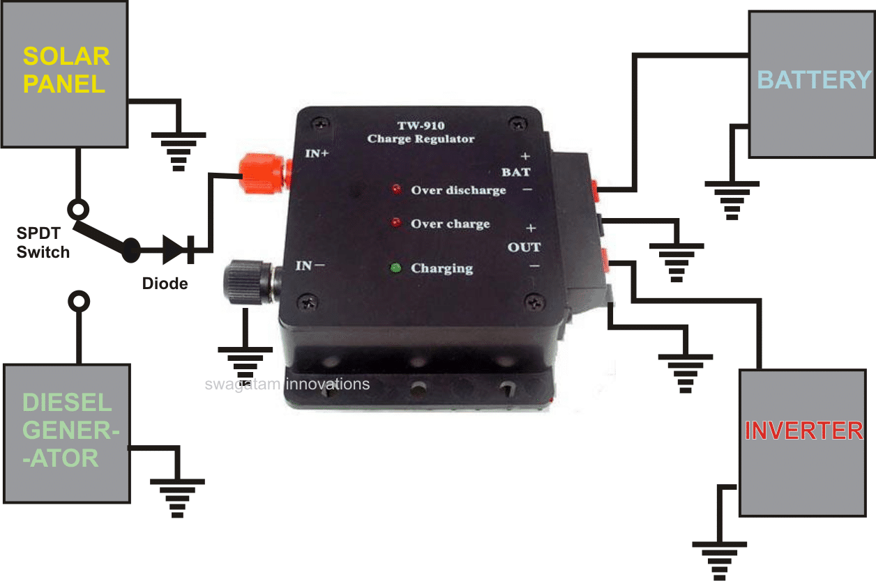
How to Wire a Solar Panel with Diesel Generator, Battery and Inverter

After you’ve procured all the above components, the fixing of the units can be started with the following steps:
- Install the panels over the roof of your house, such that it faces straight into the sky. This orientation ensures that the panel remains exposed to the sun light during most of the time between day break and dusk.
- The above position should provide a maximum of 24 volts when the sun light is perfectly incident over the panel and around 12 volts during twilight periods.
- You can check the output voltage from the panel, using a multitester (DC volt range) when there’s sufficient daylight over the panels.
- Next comes the testing of the battery charger/regulator unit, it can be done by temporarily connecting its inputs to the solar output voltage (around 15 to 20 volts).
- Now checking the output from the regulator must read around 14 volts, this confirms the correct functioning of the unit.
- The inverter may normally need no testing as it may be done prior to buying it from the dealer.
- Now it’s time to integrate the inverter with the regulator, again that’s very simple. Just connect the output terminals of the regulator/charger to the battery input of the inverter.
- Also plug-in the inverter to the mains input line of your house electrical. You might want to take the help of a professional electrician only for this part of the connection.
- Position the charger and the inverter assembly in one corner of the house, such that they are safely placed away from heat, water and human interventions.
- The battery which is the main power storage component may now be brought into the scene and joined with the regulator’s relevant terminals (indicated as (+)(-) bat).
- Finally it’s the moment when we connected the solar panel with the above positioned units.
- Connect wires of required length to the solar panel terminals and neatly escort them to the house interior so that they can be connected to the charger relevant terminals (written as +IN and –IN).
With the above configuration done correctly as discussed and the sunlight at full throttle, your battery will start getting charged.
The regulator will monitor the charge and switches it OFF and ON as per the situation.
Assuming the battery in the charged condition initially, would require 6 hours of charging from the panels after which the inverter may be turned ON for receiving the desired AC power, preferable it must be done when it’s relatively dark inside the house.
Alternatively a diesel operated car alternator may be incorporated for feeding the inverter through another regulator assembly and a change over switch. This action will ensure an AC power to the house 24-7.
We have a 13.5kWh Tesla battery. The system all works well except in winter. We have a limit on exported power to the grid hence I want to be able to dump the excess as required. In reality the system will only dump power for a few hours in the middle of the day as our panels face east and west to try to spread production over the longest period. We have Enphase micro inverters on the panels so the system is essentially AC. As such the microinverters output can be controlled by increasing the frequency and the grid actually can do this if they choose. We have current coils to measure output to the grid and can see this output in real time. This is where I got the ldea of using another current coil to control load dump resistors. I thought that by having a separate dump system I would avoid complex interfaces with the existing system.
Instead of current coils we can use current sensing high watt resistors.
I have designed an easy looking circuit for your application, at the end of the following post:
https://www.homemade-circuits.com/solar-water-heater-with-battery-charger/
Thank you for the prompt response. I will study all the material you sent. Ian
Good day, not sure if I have the right place on your site but it seems the nearest I could find. I am interested in making a device to limit power export to the grid from an existing 5kW solar system which I want to enlarge.
The problem I have is that in winter we need more panels while in summer we are producing too much power. We are limited to 5kW power export and for winter power independence we need about 10kW of solar panels. I was thinking of using a current coil to detect the amount of power being exported and then wanted to be able to progressively switch in resistive loads of say 750W each to progressively absorb excess power with the aim being to limit power exports to say 4kW?
The current system can use frequency control to limit panel output but in summer the total power output would be too great. We have 240V 50Hz power supply.
I had in mind load sensing the export and switching in the resistive loads which would have a minimum time on period to prevent short cycling.
Do you see a practical and hopefully fairly simple way to achieve this?
Thanks for your time,
Ian
Good day, we have a related post in this website, you can view it in the following link. It is based on a rising voltage sensing concept from a wind turbine generator. However, the concept can be changed into a current sensing concept. I will try to update it soon as per your specifications, and let you know.
https://www.homemade-circuits.com/simple-electronic-load-controller-elc/