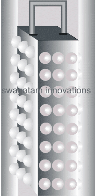
In this post I have explained how to build a simple 12V LED lantern circuit which may be used at night while travelling and outings such as in picnics, trekking, or camping etc.
Introduction
So far we have discussed white LEDs comprehensively through many of my earlier articles and have learned how efficient these lights are with power consumption.
In this article we will study a very simple configuration for making a LED lamp or a LED lantern.
New electronic enthusiasts often get confused with the wiring intricacies while configuring many LEDs in groups.
Here we’ll see how we can connect as many as 64 LEDs for making the proposed unit.
How it Works
The circuit diagram details may be understood from the following points:
White LEDs typically have a forward voltage drop of about 3 volts.
When operated at the above voltage level, the device is able to produce lights at optimum levels and the spec also maintains better life expectancy.
The minimum current required at the above voltage level is around 20 mA, which again is an optimal magnitude and is ideally suited for a white LED.
That means for driving a single white LED in the most straightforward way we would require 3 * 0.02 = 0.06 watts, that’s pretty negligible compared to the relative illumination received from it.
The best thing is that as long as the above voltage and current spec is observed, the device continues to consume 0.06 watts irrespective of the number of LEDs connected.
In the present circuit, the maximum voltage available is 12, dividing 12 by 3 = 4, meaning 4 numbers of LEDs can be accommodated at this voltage and yet we are able to limit the power to 0.06 watts.
However the above calculation would make the circuit quite vulnerable to voltage drops and if the voltage dropped even by a single volt would make the LED too dim or might just shut them OFF, we don’t want this to happen.
Therefore though the efficiency may drop a bit, we opt for a configuration which would enable the circuit to work even at lower voltages. We include only two LEDs in the series @ o.06 watts.
Now it’s all about connecting the desired number of strings of two LEDs each in parallel until all the 64 bulbs are included in the circuit.
However connecting in parallel would mean multiplying current. Since we have 32 parallel connections means the total consumption will now become 32 * 0.06 = 1.92 watts, still pretty much reasonable.
Circuit Diagram for the LED Lantern
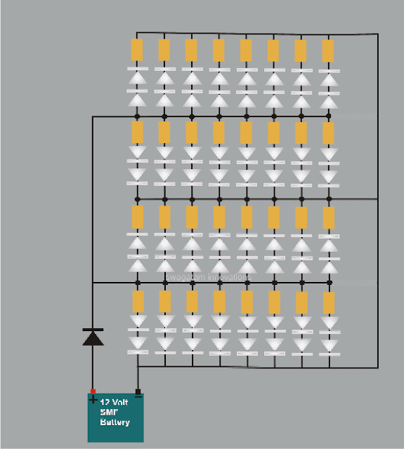
The connection details can be easily traced from the given schematic.
Your simple LED lantern is ready and may be taken anywhere outdoors with you, probably during night time explorations.
Pats List
All resistors are = 470 Ohms, 1.4 watts,
All LEDs are = white, 5mm, hi-efficiency
Diode = 1N4007


Questions & Answers
How can a faulty white LED circuit be when connected to 10 white LED with three 9 volts battery?
Sorry, did not quite get what you are asking.
thanks for the tips.
my question is, there are portable lamps with 12 leds that are powered with non-rechargeable batteries, such lamps are so simple that the batteries and the leds are connected without any protection. as a result the leds usually drain all the 1.5vx4 batteries causing damage to the batteries, and thus causing rust to the contact terminal on the device. so how can we introduce a simple feature that can cutoff the battery from overdischarge even though they are non rechargeable just to prevent the device from rusting.
Hi Abba, please refer to the following circuit, this circuit is designed to take care of both the situations, full charge and low charge cut offs…
https://www.homemade-circuits.com/solar-charger-circuit-using-transistors/
hi swagatam the issue i noticed with small flashlight portable is that the battery usually leaks within a short period therefore making the contact terminals to rust hence shorter life of the device. is there a simple solution may be a simple circuit to solve the problem. for bigger electronics usually there is low and high voltage and current cutoff features like chargers or rechargeable lamps. how about in simple non rechargeable batteries like 1.5V*4 battery powered flashlight because its extra cheap the design must be extra cheap as well. thanks in advance
Hi Abba, you can set the charging voltage to a slightly lower value than the actually specified value of the battery, this will ensure that the battery can never get fully charged, and this will also prevent the battery from leaking…or any other similar issues
Could I still build this circuit if I used 18V (2 x 9V batteries connected together) and used about 150 LEDs and 150 470Ohm resistors?
IF I could do this, how long would it light for?
Many thanks in advance.
18 – 3.3 / 0.02 = 735 ohms
470 will burn the 5mm 20 mA LEDs at 18V
as per the calculations it will need to be at least 735 ohms.
you could for a 680 ohm or even a 1K.
Thanks for your speedy answer.
Unfortunately, time is of the essence here, and I won't get the 150ohm resistors in the mail before the project is due.
Could I alternatively use a string of simply 470 ohm resistor with each individual led (in parallel) instead of 5 leds with 150ohm resistor? Like this:
│led+470 ohm resistor│
│ │
│led+470 ohm resistor│
│ │
│led+470 ohm resistor│
│ │
│led+470 ohm resistor│
│ │
│led+470 ohm resistor│
│ │
│led+470 ohm resistor│
│ │
│led+470 ohm resistor│
│ │
│led+470 ohm resistor│
│ │
│led+470 ohm resistor│
│ │
│led+470 ohm resistor│
│ │
│led+470 ohm resistor│
│ │
│led+470 ohm resistor│
etc.
Thanks again for any help you can give.
Patrick
yes it's possible just make sure each string now includes 5 LeDs in series with 150 ohms in each series
Ok thanks, if does not work I will just build one of your Emergency circuits thanks Buddy
sure…thanks!
Thanks for your reply, I did miss something I thought all white LEDS had the same (ma) rating and voltage draw, I told you I know just enough to get my self in trouble, I guess it is going to be trial and burnout method, they are free now and if I can not make them work I was going to throw them away anyway, going to hook them as they are to a 5 volt phone charger first to see if they burn or burn HA HA, it is never easy when you are trying to recycle free electronics< if you do not snap, crackel and pop you are not learning, that is like I crashed 3 computers before I learned how to use dos and now you use windows do not need dos, thanks Buddy
sure buddy, you won't learn unless you sacrifice a few of the valuable things…
you can experiment on a single LED, by applying 12V to it through an arbitrarily selected high value resistor such as a 1K, then go on reducing this value until you find the resistor getting to hot or may be the LED on the verge of getting destroyed, this will tell you which value of resistor was actually optimal during the procedure…
wish you all the best.
thanks for the help, So I am confused if you have an white led with a 32 ohm resistor you can not just add another resistor to use with 12 volt batt, what about just taking that resistor out and just replacing it with one that works with 12 volts, I think I will make it easy just cut that resistor out put in a jumper in to connect two LEDS and put in the resistor you have shown above and be done with it, what do you think, or am I missing something which is almost all ways, thanks for your thoughts, buddy
either I have to know the original voltage spec used in the unit, or you can tell me the LED current (mA) rating…any of the two will be sufficient for calculating the resistor value….if neither of this is known then it would be impossible to calculate the correct resistor value.
the other method is to try by trial and error method which can be fatal for the LED or can make them work inefficiently
Thanks for the help, I do not know the supply voltage the bat went dead and would not charge and it does not have any markings on it or the light all it has is a marking of a number of the circuit board, SS272-B one of those china made or some place does not have a brand name, sorry Buddy
OK but without the voltage I wouldn't be able to calculate the resistor value…so it can be difficult to configure the design
Ok thanks. My question is the two lights I have is one has 7 LEDS in
parallel with a 32 ohm resistor at each light and 5 in parallel with
one 6.8m ohm resistor up front, can you just add another resistor to make
them work off 12 volts if so what sizes please or do I need to rewire
the whole thing, Just a little about me I took half a course in
electronics about 45 years ago, so I know what things do and how to
take them apart and replace parts but I missed or forgot the part about
building circuits, I can build from a DWG, so I am half smart, If I was
totally smart I would build me a overunity motor or magnet motor, just
love that stuff, Many thanks Buddy
OK, but I'll also need to know what supply voltages these two lamps used…only then I'll able to judge the LED specs and then accordingly would be able to tell you the resistor value and the wiring detail for connecting these together with a 12V supply.
thanks for the info, I was wondering if you can take old LEDS from old LED flash lights that have quit working and make a simple working light for hooking to a 12 volt battery to make a light for when the power goes out.
If the LEDs are in a a working condition then definitely you can use them with an external battery for emergency lighting….
good day! is it the same process if i use different color of led light for my lantern?
if you use approximately 3.3V LEDs then it'll be the same regardless of the color…
Thanx
Ok sir but….. I want to send a video to u so that's why I wanted ur email……….
OK, send it to:
hitman2008(at)live.in
replace (at) with @
Thanks for the reply…………. Sir I want ur email address……….
for discussing circuits you can feel free to ask your questions here….I use email only for business related discussions.
Can I use piranha led if yes then ampere for piranha led will be 4AH or it is changed and wat will the resistor value for piranha led and 1watt led…. Thanks
yes you can use piranha LEDs also without changing anything in the circuit,
but 1 watt leds cannot be used in this circuit, it will require completely different configuration
Wat is the ampere of battery
for 5mm leds it can be 4AH, and for 1 watt it should be 25Ah or 40 AH
Dear sir,
May I know which software is used to draw the schematic in this post?
Thank you.
Dear Srinivas, I use CorelDraw……
resistors can be connected anywhere in the line, the position is not important.
Each of the shown Two LEDs with the series resistor becomes one string, count how many are there.