• Skip to main content
  • Skip to primary sidebar

Homemade Circuit Projects

Need circuit help? Post them in the comments! I've answered over 50,000!

Blog | Categories | About | Contact | Calculators-online
You are here: Home / Battery Charger Circuits / Battery Charger Problems Troubleshooting Discussed

Battery Charger Problems Troubleshooting Discussed

Last Updated on August 3, 2019 by Swagatam 14 Comments

The included battery charger circuit was designed and built by Mr.Vinod Chandran, however there's some issues and problems  with the circuit the troubleshooting of the same is addressed in this article. I have explained the discussion between Vinod and me.

Table of Contents
  • Discussing a Transistor Battery Charger Problem

Discussing a Transistor Battery Charger Problem

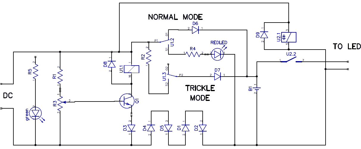
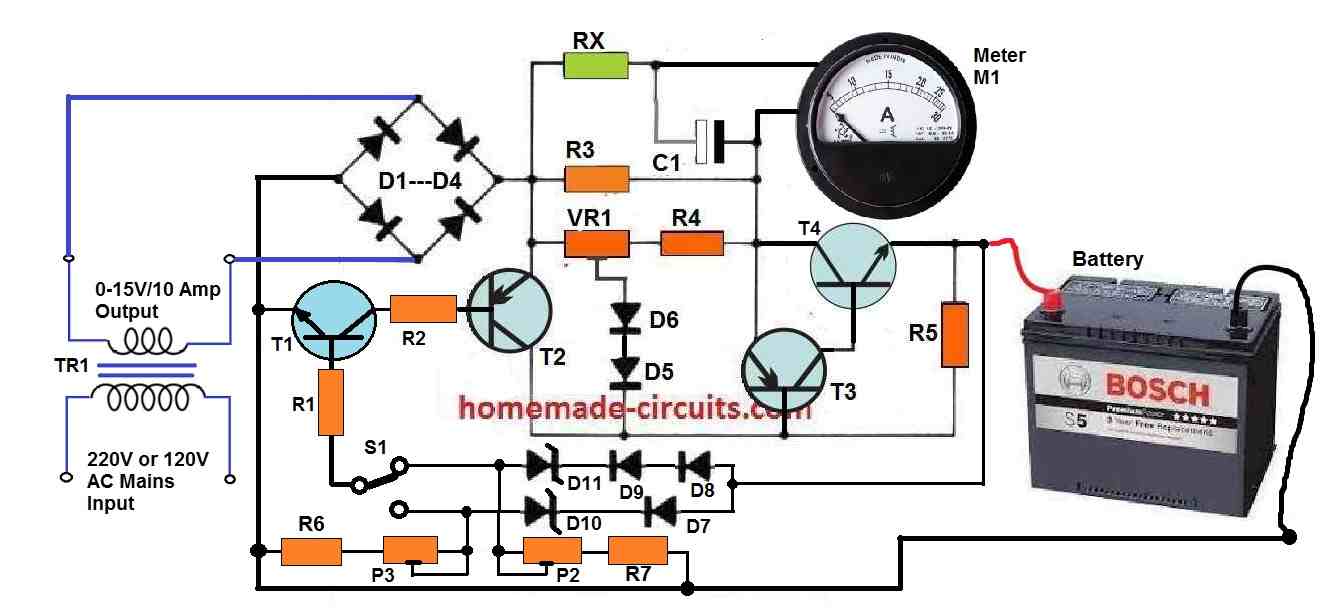
Vinod: I am attaching the circuit image of the charger with hysteresis feature. (with my modification.). This charger is working good. But i need your suggestions and confirmation.

warning message: electricity is dangerous, proceed with caution
batterycharger

Swagatam: Using a transistor won't give accurate results, moreover the setting part would become very tedious. The circuit is technically correct, if you can adjust the tripping point correctly, then it might just work.

Vinod: I am going to test this circuit. I already build this in general board. automatic cut-off is set in 13.6v now. All i want to wait for the battery to discharge around 12v. I will inform you the result.

Vinod: I made the charger (hysteresis) but there is a problem. i will attach the image to explain the problem. When i connect multimeter in that particular red dots, the voltage shows 16.8.(0.43 A) but when i disconnect battery from the charger and measured again. then there is no problem. the out put is 14.2. And the other pin of the relay(through the current limiting resistor) will deliver a clean output voltage of 13.9 (0.033A). Why this is happening ?. The only change i have made from this circuit is to grab the green LED and R1 from there and connect it after the D6.

modifiedbatterychargercircuit

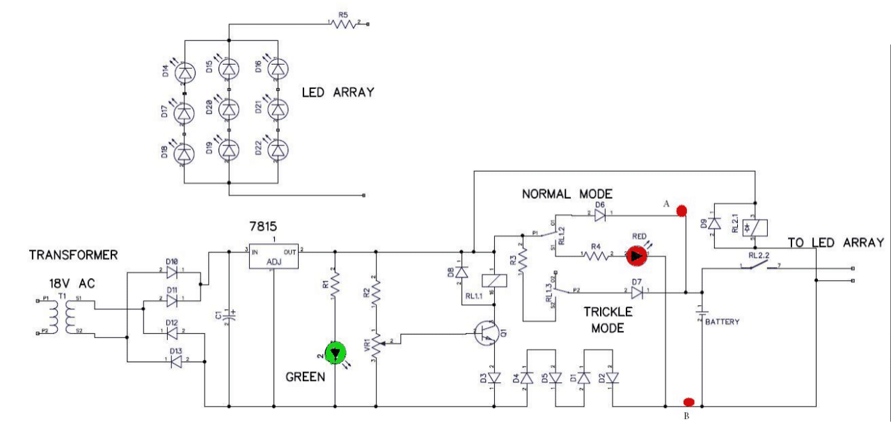
Swagatam: It's difficult to understand and troubleshoot the fault, if you are connecting meter prods across the battery terminals, it should show the dropped voltage level of the battery ... this problem can happen only if the source current is too high and not at the recommended 1/10th level of the battery AH, make sure to use an input that is specified with the above current limit

You can repeat the checking by switching OFF the power supply and then again switching ON the power supply keeping the meter connected to the points A and B.

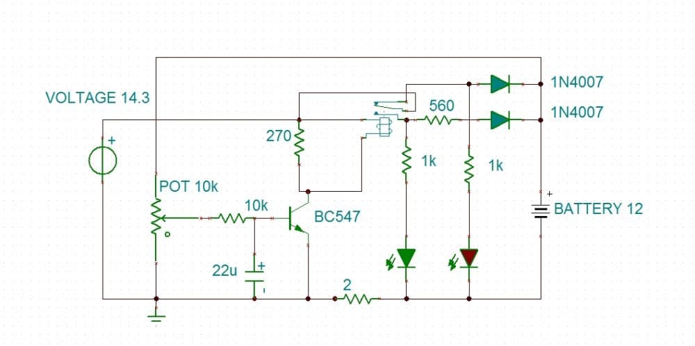
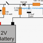
Hi Swagat, At last i made a charger that suits my needs. this is the schematic.(plz look attachment). Until battery gets 13v this is a constant current charger(400-500mA). After 13v, charging current is 25mA. And the LED's indicate the charging stages. Regards Vinod chandran

batterychargercircuit

You'll also like:

  • 1.  12 V to 19 V Boost Converter Circuit
  • 2.  Battery Full Charge Indicator Circuit using Two Transistors
  • 3.  4 Simple Li-Ion Battery Charger Circuits – Using LM317, NE555, LM324
  • 4.  Designing a Customized Battery Charger Circuit
  • 5.  How to Switch Two Batteries Manually using Opto Coupler
  • 6.  High Voltage Battery Charger Circuit

About Swagatam

I am an electronics engineer with over 15 years of hands-on experience. I am passionate about inventing, designing electronic circuits and PCBs, and helping hobbyists bring their projects to life. That is why I founded homemade-circuits.com, a website where I share innovative circuit ideas and tutorials. Have a circuit related question? Leave a comment.... I guarantee a reply!

Previous Post: « Make a Football Electricity Generator Circuit
Next Post: LM386 Amplifier Circuit [Working and Application Circuits] »

Reader Interactions

Comments

  1. Vaishnavi AH says

    August 23, 2024 at 10:19 am

    Respected Sir,

    I am working as a Hardware Trainee in EV. I wanted to learn circuit designing and work in my Electronics core. Please assign me some small circuits so that i can try to design them. Please don’t hesitate to reply to my questions.

    Thanks and Regards
    Vaishnavi AH

    Reply
    • Swagatam says

      August 23, 2024 at 10:52 am

      Hello Vaishnavi,
      Please go to the following page and let me know which concept looks most suitable for you to start with.
      https://www.homemade-circuits.com/circuit-projects-for-beginners-and-school-students/
      Please comment under the above post, then we can start the tutorials.

      Reply
  2. Vaishnavi AH says

    August 22, 2024 at 10:51 am

    How to design circuits, I am a fresher. Guide me in my career

    Reply
    • Swagatam says

      August 22, 2024 at 2:10 pm

      You will have to start learning by building small circuits and how they work and how to troubleshoot them, and then gradually go for bigger designs…if you any problems understanding them you can consult me here, I will try to figure it out for you…

      Reply
  3. suat says

    December 1, 2023 at 3:45 pm

    Hi Mr. Swagatam;
    I have scrap battery charger and its output is for the 72V 8A. But I have no battery to test it. I would like test if voltage / current will collapse or not while charging. So it is possible to test it with indoor apliances like freezer bulb or similiar.

    Reply
    • Swagatam says

      December 1, 2023 at 4:20 pm

      Hi Suat, yes it is possible to test the power supply output response by connecting a dummy load such as an appropriately rated incandescent bulb…

      Reply
      • suat says

        December 1, 2023 at 11:33 pm

        thanks for the kind support.
        I am not engineer so I am not able to do but I think it maybe about 700 Watt and so it may be around
        220V 3A incandescent bulb. Nevertless I am not sure about it.

        Reply
        • Swagatam says

          December 2, 2023 at 8:25 am

          Suat, The bulb current rating and volage rating must be identical to the power supply rating, only then the actual response can be analyzed

          Reply
  4. Dayo says

    January 10, 2018 at 2:58 pm

    Please how can I modify this for 15amps charging amps

    Reply
    • Swagatam says

      January 10, 2018 at 7:22 pm

      by using a relay with contacts rated at 20 amps

      Reply
      • Dayo says

        January 13, 2018 at 5:57 pm

        Thanks sir, I used my modified sine inverter to charge lead acid Battery but didn’t charge but charged with utility supply, why.

        Reply
        • Swagatam says

          January 14, 2018 at 11:31 am

          If you are using an inverter for charging a battrey then the inverter battery must be 5 times larger than the battery which is being charged…..only then you will find it getting charged…but this does not make much sense

          Reply
          • Dayo says

            January 16, 2018 at 4:27 am

            Thanks sir for educating me, for knowledge reason, I want to ask why does 1kva generator set will charge the battery but 1kva inverter will not charge.

            Reply
            • Swagatam says

              January 16, 2018 at 11:34 am

              check the current with an ammeter for the two sources while charging the battery, that will explain the reason behind it.

              Reply

Need Help? Please Leave a Comment! We value your input—Kindly keep it relevant to the above topic! Cancel reply

Your email address will not be published. Required fields are marked *

Primary Sidebar

Subscribe to New Circuit Ideas

Categories

  • Arduino Projects (87)
  • Audio and Amplifier Projects (132)
  • Automation Projects (17)
  • Automobile Electronics (101)
  • Battery Charger Circuits (83)
  • Datasheets and Components (104)
  • Electronics Theory (143)
  • Free Energy (37)
  • Games and Sports Projects (11)
  • Grid and 3-Phase (19)
  • Health related Projects (25)
  • Home Electrical Circuits (12)
  • Indicator Circuits (14)
  • Inverter Circuits (87)
  • Lamps and Lights (142)
  • Meters and Testers (69)
  • Mini Projects (46)
  • Motor Controller (64)
  • Oscillator Circuits (27)
  • Pets and Pests (15)
  • Power Supply Circuits (108)
  • Remote Control Circuits (50)
  • Security and Alarm (64)
  • Sensors and Detectors (101)
  • Solar Controller Circuits (59)
  • Temperature Controllers (42)
  • Timer and Delay Relay (49)
  • Transmitter Circuits (29)
  • Voltage Control and Protection (37)
  • Water Controller (36)

Calculators

  • Battery Back up Time Calculator
  • Capacitance Reactance Calculator
  • IC 555 Astable Calculator
  • IC 555 Monostable Calculator
  • Inductance Calculator
  • LC Resonance Calculator
  • LM317, LM338, LM396 Calculator
  • Ohm’s Law Calculator
  • Phase Angle Phase Shift Calculator
  • Power Factor (PF) Calculator
  • Reactance Calculator
  • Transistor Astable Calculator
  • Transistor base Resistor Calculator
  • Voltage Divider Calculator
  • Wire Current Calculator
  • Zener Diode Calculator
  • Filter Capacitor Calculator
  • Buck Converter Calculator
  • Boost Converter Calculator
  • Solar Panel, Inverter, Battery Calculator
  • Wire Current Calculator
  • SMPS Transformer Calculator
  • IC SG3525, SG3524 Calculator
  • Inverter LC Filter Calculator

People Also Search

555 Circuits | 741 Circuits | LM324 Circuits | LM338 Circuits | 4017 Circuits | Ultrasonic Projects | SMPS Projects | Christmas Projects | MOSFETs | Radio Circuits | Laser Circuits | PIR Projects |

Recent Comments

  • Swagatam on 10 LED Tachometer Circuit Diagram
  • Swagatam on How Shunt Regulator TL431 Works, Datasheet, Application
  • Göran on 10 LED Tachometer Circuit Diagram
  • SA on How Shunt Regulator TL431 Works, Datasheet, Application
  • Swagatam on Adjustable 0-100V 50 Amp SMPS Circuit

Company

  • Privacy Policy
  • Cookie Policy
  • About Me
  • Contact
  • Disclaimer
  • Copyright
  • Videos
  • Sitemap

Social Profiles

  • Twitter
  • YouTube
  • Instagram
  • Pinterest
  • My Facebook-Page
  • Quora
  • Stack Exchange
  • Linkedin
  • © 2025 · Swagatam Innovations