In this article I have explained a very simple yet amusing mains operated xenon tube flasher circuit using ordinary electronic components.
Circuit Operation
The circuit was taken from one of the old elektor electronics magazine and it is indeed a very cute little circuit which may be used for creating high intensity lighting effects during festivals, parties and fun gatherings.
The circuit may be understood by referring to the diagram and with the following explanations:
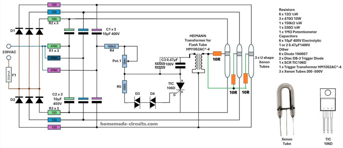
Diodes D1 and D2 along with the capacitors C1 and C2 form a voltage doubler circuit which creates a voltage level twice the value of the input voltage (across C1/C2).
Resistors R4 along with R5 and P1 provides the gate current to the triac so that it can fire for the required actions.
However the triac is unable to fire until the voltage reaches above the diac firing voltage which is around 60 volts (due to D3/D4).
Once this happens the triac triggers, inducing a momentary pulse inside the primary winding of the pulse transformer via C3.
This in turn jumps a high voltage pulse into the secondary of the transformer which is connected to the trigger wire of the xenon bulb.
The xenon bulb triggers due to the above actions passing the entire voltage across C1/C2 through it.
This generates a blinding arc light inside the tube, producing the required high intensity flash.
However once the tube fires C1/C2 completely discharges making the gate voltage of the triac fall to zero switching OFF the xenon bulb instantly
The whole circuit returns to its original condition until C1/C2 charges up again and repeats the cycle.
Thus the flashing keeps repeating as long as mains power stays connected at the input.
Parts List
| Reference | Component Type | Value / Rating | Key Specifications |
|---|---|---|---|
| F1 | Fuse | 500 mA | 250 V AC, Fast-blow |
| D1 | Diode | 1N4007 | 1 A, 1000 V PIV, 30 A surge, 1.1 V drop |
| D2 | Diode | 1N4007 | 1 A, 1000 V PIV, 30 A surge, 1.1 V drop |
| D3 | Diode | BR100 | 1000 V PIV, 1 A, recovery 2–3 µs |
| D4 | Diode | BR100 | 1000 V PIV, 1 A, recovery 2–3 µs |
| R1 | Power Resistor | 470 Ω 10 W | ±5%, wire-wound, 10 W |
| R2 | Resistor | 12 Ω | 1/4 W or 1/2 W, ±5% |
| R3 | Resistor | 12 Ω | 1/4 W or 1/2 W, ±5% |
| R4 | Resistor | 150 kΩ | 1/4 W, ±5% |
| R5 | Resistor | 330 Ω | 1/4 W, ±5% |
| P1 | Potentiometer | 1 MΩ | Linear type, 0.25 W |
| C1 | Electrolytic Cap | 8 µF 350 V | 350 V DC, ripple ≥ 300 mA, ESR ≤ 0.5 Ω |
| C2 | Electrolytic Cap | 8 µF 350 V | 350 V DC, ripple ≥ 300 mA, ESR ≤ 0.5 Ω |
| C3 | Capacitor | 1 µF 100 V | Polyester/NP, 100 V DC, ±10% |
| Th1 | SCR | TIC106D | 400 V, 4 A RMS, 30 A surge, 200 mA gate, Igt 200 µA |
| Tr1 | Trigger Transformer | --- | Primary ~200–300 turns, Secondary 8–12 kV pulse, 2–5 mA |
| La1 | Xenon Flash Tube | --- | Trigger 2–5 kV, Operating 250–350 V, Pulse current 50–200 A |
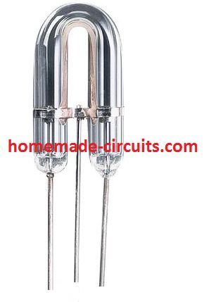
Xenon Tube
As the name suggests, it's a tube filled with inert xenon gas. A metal ring is attached toward the anode side of the tube which becomes the gate trigger point of the device. This ring is terminated with a wire so that it can be connected with s pulse source.
When a high voltage is set across the anode/cathode pins of the tube and a pulse applied across the trigger gate wire and cathode, the tube gets charged up and allows the whole voltage across its Anode/cathode to pass through creating an intense arc lighting inside the tube due to the passage of the high speed electrons through the xenon gas.
Any standard xenon tube can be used here, preferably the ones which are used in electronic cameras.
Pulse Transformer Construction
The transformer may be built by winding 100 turns of 36 SWG wire over a tiny ferrite core. This becomes the secondary winding (A to B)
And about 10 turns of 22 SWG over the above winding. This becomes the primary winding of the transformer (A to C)


Questions & Answers
Thanks for the speedy help and support. Will start on the build and post back on how things go.
Sure, no problems..
Hi Ankush,
Thanks for posting your strobe circuit and description.
I have modified your circuit to drive 3 Xenon Tubes in a strobe I built many years ago.
My hope is to obtain a flash with higher intensity and shorter flash duration than that achieved in the original unit that used lower anode voltage & higher capacitance.
Before I build the circuit, I would value your opinion. Would you take a look at the below link and comment as necessary.
Many thanks,
Peter
Hi Peter,
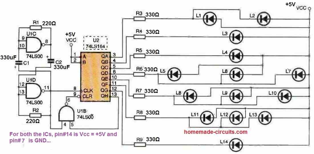
I checked your link and modified the design further, and it looks perfect now, and will drive the 3 strobe lamps uniformly and correctly, here’s the image link:
Hi Swagatam Sir,
I tried with two 500 watt xenon linear tubes from a friend. but I think neither coils are not properly turned nor the transformer. Kindly help.
how do I serially connect the lamps for bright flash glow?
I want single [1] flash at full power in every 9 second only with manual push button. Possible? please help. I am making an Exposure box for my small print shop. I am not able to afford so much money to buy from Kolkata market. I am struggling to make one. lease please help me. you can kindly mail me a proper hand drawn circuit diagram? my mail ID: calcuttacity[at]gmail.com
…you may put a push button in sereis with R4 for getting a push button trigger facility…
Hi Udyog,
The circuit was taken from the elektor electronic magazine, so I won't be able to suggest much about the modifications.
However for increasing the brightness you could try the following tweaks:
1) try a relatively thicker wire for the secondary winding, may be a 32 SWG instead of 36.
2) Increase the values of C1/C2 to 10uF/350V.
3) Increase the value of C3 by connecting another 1uF in parallel with the existing capacitor.
4) try a neon bulb in place of the two series diacs….the neon bulb must be a good quality type as shown below
hi swagatam sir, I am following your posts for many days. I have found the same circuit in a bpb book, but I can not understand if i want to flash two 500 watt xenon lamp in variable rate and can control brightness, what shall be the circuit? in which brand name xenon strobes are available in india? kindly help.please e-mail me a circuit.
Hi Adin, P1 can be used for adjusting the flashing rate or the speed, while the value of C3 could be changed for getting some sort of difference in the intensity of the xenon discharges.
I am not sure about the xenon brand names, the shopkeeper will be able to guide you better
Hi Swagatam , Can I use a 1000W Xenon Lamp of Osram make for the above purpose?
Hi Ankush, a 1000W xenon tube will work with the above circuit but only after the coil and the triac are modified appropriately for handling the massive power of the tube.
Hi Swagatam ur blog is very useful. I need a circuit – 20 volt dc output with 500 mA.input is 230 volt ac.
Hi Vijay, thanks, I'll try to design it and discuss it in my blog soon.