• Skip to main content
  • Skip to primary sidebar

Homemade Circuit Projects

Need circuit help? Post them in the comments! I've answered over 50,000!

Blog | Categories | About | Contact | Calculators-online
You are here: Home / Automobile Electronics / LED Tail Ring Light Circuit for your Car

LED Tail Ring Light Circuit for your Car

Last Updated on August 14, 2019 by Swagatam 8 Comments

In the following post I have explained a fancy LED sequencing/diverging ring light circuit which can be used as a tail brake light  in cars. The idea was requested by one of the avid readers of this blog, Mr. Bobby. I have explained more.

Table of Contents
  • Technical Specifications:
  • The Design

Technical Specifications:

Hello,

I was just reading thru your wonderful article on building an LED chasing tail light:https://www.homemade-circuits.com/how-to-make-car-led-chasing-tail-light/

Could this circuit be adapted to create a round tail light that lights rings in sequence from the center out as the brake is pressed, one ring at a time until all the LEDs are lit and then flash all the LEDs twice and keep all LEDs lit solid after? If not, could you design a circuit that would?

I would be willing to pay for your time.
Thank you,

Bobby

The Design

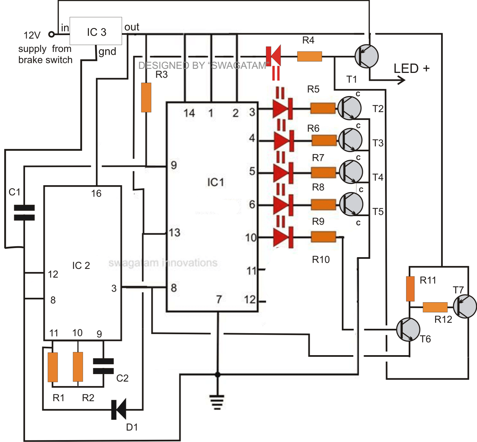
The circuit diagram shown below has been designed as per the above request, I have explained its functioning with the following points:

IC1 which is a "serial shift resistor"  forms the heart of the entire circuit, the main function of this IC is to illuminate the LEDs connected to pin outs #3-4-5-6-10-11-12-13 in a sequence, keeping the sequence latched and illuminated as it proceeds. This happens in response to each clock pulse applied at pin#8 of the IC.

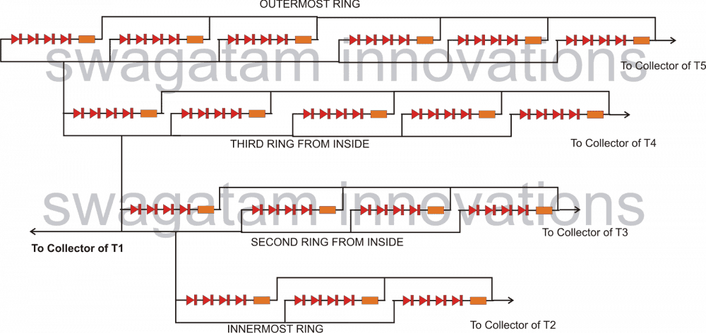
The LEDs which are triggered by the pin#3-4-5-6 and 10 are arranged as rings such that it illuminates from inner most ring first toward the outermost ring, producing an interesting and visually rich effect.

And that's not all, after the above effect the whole illuminated group of arrays flash  thrice and then shut off.

The above "show" repeats every time brakes are applied.

When brakes are applied, battery voltage connects with the circuit initiating the following operations:

C1 resets IC1 such that the sequence begins from pin#3 and not from any other in between pin out (this output illuminates the inner most ring).

IC2 is an oscillator IC which generates the required clocks for the IC1 from its pin#3.

In response to the above clocks, the sequence proceeds creating the desired diverging illumination effects, until it reaches pin#10.

The LEDs receive the required positive supply through T1 which stays triggered  due to the low logic at pin#13 of IC1

When the sequence reaches pin#10, T6 conducts which also switches ON T7.

The emitter of T6 is connected to pin#3 of IC2 which is already generating the clocks for the required of IC1.

The alternating low pulse from this pin out switches T6/T7 in a blinking mode.

T7, in response to the above blinking, sends correspondingly pulsating positive pulses to base of T1.

This in turn forces T1 to flash the LEDs in accordance with the above influence.

The illuminated ring arrays start flashing until the sequence is forwarded to pin#13.

The moment pin#13 becomes high, T1 switches OF and also the "high" reaches pin#11 of  IC2.

IC2 locks and stops the clocks at pin#3.

The whole operation freezes.

The above system breaks and repeats itself only as soon as the brakes are released and pressed afresh.

fancyLEDcartaillightcircuit

The LEDs which needs to be connected across the collectors of T1 and T2/T3/T4/T5 may be wired up in the following manner. The arrangement should be designed in a circular manner to form the corresponding RINGs.

cartaillightLEDsetupdiagram

Parts List

  • R1 = 2M2
  • R2 = TO BE EXPERIMENTED
  • R3 = 1M
  • R4---R12 = 2K2
  • T1 = 8550 or 2N2907
  • T2----T6 = BC547
  • T7 = BC557
  • D1 =1N4148
  • C1,C2 = 0.1uF
  • IC1 = 74LS164
  • IC2 = 4060
  • IC3 = 7812

ALL LEDS = RED 5MM, ASSOCIATED RESISTORS ARE ALL 150 OHMS, 1/4 WATT

You'll also like:

  • 1.  How to Make a Car Power Window Controller Circuit
  • 2.  Automatic Vehicle Headlight Dipper/Dimmer Circuit
  • 3.  LED Lamp Circuit for Motorbike Headlamp
  • 4.  How to Make Car LED Bulb Circuit
  • 5.  Automotive Trailer Lights Interface Circuit
  • 6.  Automotive LED Driver Circuits – Design Analysis

About Swagatam

I am an electronics engineer with over 15 years of hands-on experience. I am passionate about inventing, designing electronic circuits and PCBs, and helping hobbyists bring their projects to life. That is why I founded homemade-circuits.com, a website where I share innovative circuit ideas and tutorials. Have a circuit related question? Leave a comment.... I guarantee a reply!

Previous Post: « Solving LDR Controlled LED Emergency Lamp Problem
Next Post: Generator/Alternator AC Voltage Booster Circuit »

Reader Interactions

Comments

  1. Childs says

    August 13, 2019 at 11:57 pm

    Amazing.

    This is now added to my “To do list”.

    Thank you for your hard work Swagatam. It kinda feels wrong to receive such education for free.

    Reply
    • Swagatam says

      August 14, 2019 at 11:46 am

      It’s my pleasure Childs, appreciate your thoughts!

      Reply
  2. Jon Richey says

    May 29, 2017 at 8:27 am

    "And that's not all, after the above effect the whole illuminated group of arrays flash thrice and then shut off.

    The above "show" repeats every time brakes are applied."

    Is it possible to have them stay on solid after the sequence as long as the brake is on?
    Thanks
    Jon

    Reply
    • Swagatam says

      May 29, 2017 at 11:51 am

      yes that may be possible if you disconnect the D1 anode from pin#13 and connect it to pin#1 of IC1….

      Reply
  3. Jon Richey says

    May 29, 2017 at 5:58 am

    Hi Swagatam great work as always.
    Couple of questions you say:
    "Yes those are LEDs which indicate the tail light functioning and must be installed somewhere around the dashboard."
    Can the LEDS from IC1 pins 3,4,5,6 and 10 be replaced with a 1N4007 diode?
    Can this function as a solid lit tail light also?

    Reply
    • Swagatam says

      May 29, 2017 at 11:39 am

      Thanks John,

      Yes they can be replaced with diodes but that won't lead to anything, if you want to eliminate the LEDs you can simply replace them with wire links….

      Reply
  4. abhinav kaushik says

    August 27, 2013 at 6:57 pm

    thanks for such wonderful information …simply want to know can i use other resistance instead of 150 ohm with LEDs plz reply

    Reply
    • Swagatam says

      August 28, 2013 at 7:39 am

      yes you can use other closer values which might result in different intensities over the LEds

      Reply

Need Help? Please Leave a Comment! We value your input—Kindly keep it relevant to the above topic! Cancel reply

Your email address will not be published. Required fields are marked *

Primary Sidebar

Subscribe to New Circuit Ideas

Categories

  • Arduino Projects (87)
  • Audio and Amplifier Projects (132)
  • Automation Projects (17)
  • Automobile Electronics (101)
  • Battery Charger Circuits (83)
  • Datasheets and Components (104)
  • Electronics Theory (143)
  • Free Energy (37)
  • Games and Sports Projects (11)
  • Grid and 3-Phase (19)
  • Health related Projects (25)
  • Home Electrical Circuits (12)
  • Indicator Circuits (14)
  • Inverter Circuits (87)
  • Lamps and Lights (142)
  • Meters and Testers (69)
  • Mini Projects (46)
  • Motor Controller (64)
  • Oscillator Circuits (27)
  • Pets and Pests (15)
  • Power Supply Circuits (108)
  • Remote Control Circuits (50)
  • Security and Alarm (64)
  • Sensors and Detectors (101)
  • Solar Controller Circuits (59)
  • Temperature Controllers (42)
  • Timer and Delay Relay (49)
  • Transmitter Circuits (29)
  • Voltage Control and Protection (37)
  • Water Controller (36)

Calculators

  • Battery Back up Time Calculator
  • Capacitance Reactance Calculator
  • IC 555 Astable Calculator
  • IC 555 Monostable Calculator
  • Inductance Calculator
  • LC Resonance Calculator
  • LM317, LM338, LM396 Calculator
  • Ohm’s Law Calculator
  • Phase Angle Phase Shift Calculator
  • Power Factor (PF) Calculator
  • Reactance Calculator
  • Transistor Astable Calculator
  • Transistor base Resistor Calculator
  • Voltage Divider Calculator
  • Wire Current Calculator
  • Zener Diode Calculator
  • Filter Capacitor Calculator
  • Buck Converter Calculator
  • Boost Converter Calculator
  • Solar Panel, Inverter, Battery Calculator
  • Wire Current Calculator
  • SMPS Transformer Calculator
  • IC SG3525, SG3524 Calculator
  • Inverter LC Filter Calculator

People Also Search

555 Circuits | 741 Circuits | LM324 Circuits | LM338 Circuits | 4017 Circuits | Ultrasonic Projects | SMPS Projects | Christmas Projects | MOSFETs | Radio Circuits | Laser Circuits | PIR Projects |

Recent Comments

  • Swagatam on Anti Spy RF Detector Circuit – Wireless Bug Detector
  • Swagatam on Buck Converter Calculator
  • Christian on Anti Spy RF Detector Circuit – Wireless Bug Detector
  • Swagatam on Best 3 MPPT Solar Charge Controller Circuits for Efficient Battery Charging
  • Dan on Buck Converter Calculator

Company

  • Privacy Policy
  • Cookie Policy
  • About Me
  • Contact
  • Disclaimer
  • Copyright
  • Videos
  • Sitemap

Social Profiles

  • Twitter
  • YouTube
  • Instagram
  • Pinterest
  • My Facebook-Page
  • Quora
  • Stack Exchange
  • Linkedin
  • © 2025 · Swagatam Innovations