This digital frequency counter will provide a direct reading of the frequency applied at its input, through a 5 digit common cathode display module.
The compact frequency counter can be used for accurately counting the frequency or pulse from any intended source.
Main Applications
It can be also used for measuring the RPM of a rotating object by checking the digital frequency reading with a corresponding stop watch. The reading on the display after 1 minute will provide the user with the RPM value of the source.
Another useful use of this digital pulse counter is for measuring the frequency of an inverter, or for checking the proper working of the oscillator of an inverter.
The project can be also applied in delay timer circuits for measuring the delay ON or delay OFF output pulse, and the time required for the output, to set the timing component values correctly.
About IC 4033
The IC 4033 is composed of a 5 stage Johnson decade counter and an output decoder which is designed to convert the Johnson code to a 7 segment decoded output.
This decoded output is used for driving a single stage of a digital display module. This IC is especially is extremely well suited in display programs which demand low power consumption and compactness.
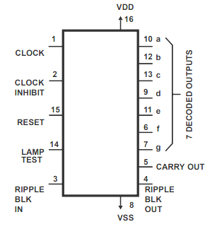
A high logic on the RESET pin restores the decade counter to its intial zero display position. The counter is designed to move by a single count in response to the positive clock freqeuncy input when the CLOCK INHIBIT signal is provided with a low logic supply.
Counter progression by means of the clock rail is prevented and stopped as soon as the CLOCK INHIBIT is applied with a HIGH logic input.
The CLOCK INHIBIT logic input could be applied as a negative-edge clock in case the clock line is applied with logic high. Antilock gating is offered within the JOHNSON counter, which ensures correct sequencing for the counting process.
The CARRY-OUT (Cout) signal finishes a single cycle every ten CLOCK INPUT cycles and it is implemented to clock the next up decade instantly in a multi-decade counting chain.
The seven decoded outputs (a, b, c, d, e, f, g) light up the appropriate sections in a 7-segment display module intended for addressing the decimal figures 0 to 9.
Circuit Working
The 5 digit frequency counter circuit discussed below is made using five decade-counter IC's (IC1 through IC5) and their complementing 7 segment displays (DIS1 through DIS5).
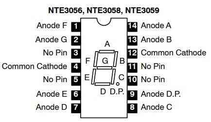
The ICs used for this project are IC 4033, while the displays are 7-segment common cathode NTE3056 or similar.
The complete schematic of the proposed 5 digit frequency pulse counter is shown below.
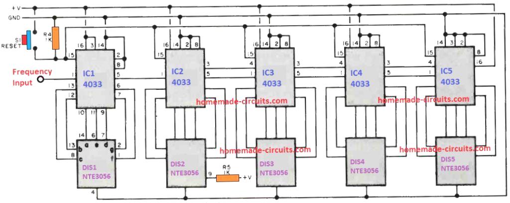
The design is basically the identical repetition of 5 pulse counter stages comprising of IC1 and the DIS1 in a sequentially cascaded format.
It must be note that DIS2 is the only display module which has an active decimal point. This decimal point illuminates as soon as the supply to the circuit is switched ON.
The frequency or the pulse which needs to be counted and displayed over the 7-segment displays is applied to the pin#1 of IC1.
As soon as the frequency is applied, the displays begin showing the number of elapsed pulses of the frequency.
If the frequency input is removed, the count over the display will get latched and remain available until the switch S1 is pressed, or the power is switched OFF and ON again.
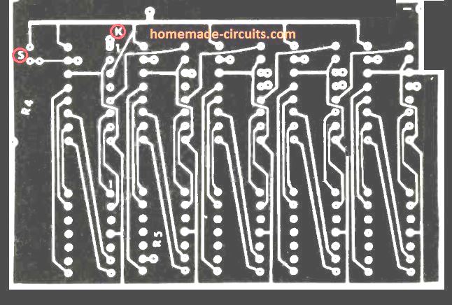
PCB Design for the 5 Digit Frequency Counter
The following image shows the track side PCB layout for the 5 digit frequency counter circuit.
10 MHz Digital Frequency Meter
Figure 1 exhibits the circuit diagram of the 10-MHz digital Frequency Counter. The circuit includes an ICM7208 seven-decade counter (U1), an ICM7207A oscillator controller (U2), and a CA3130 biFET op amp (U3). IC U1 is used for counting the input signals, and then decode them to 7-segment structure. It additionally is used for generating the output signals for driving a 7-digit LED display.
IC U2 is wired to supply the timing clocks for U1, while U3 processes the input signal to deliver an appropriate waveform for the U1 input. The frequency from the 5.24288 MHz crystal is divided by U2 to generate a 1280 MHz multiplexing signal at pin 12 of U2. This signal is applied to the input of U1 at its pin 16 which is utilized to scan the display digits in succession. The cathodes of each one digit are switched to ground repeatedly every second, triggering any segment of the digits which have their anodes high due to the decoding by U1.
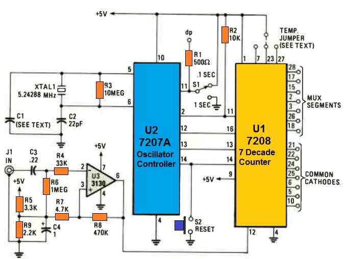
The frequency from the crystal is additionally divided to generate a short "store" pulse on pin 2 of U2, which is followed by a brief "reset" pulse on pin 14 of U2 (after around 0.4 milliseconds). The pulse frequency is established by the state of the pin 11 of U2.
As soon as U2 pin 11 is switched to ground via S1, the pulses repeat every 2 seconds and result in U2 pin 13 to turn high for a single second. This inhibits further input signals from getting into U1. This leads to the U1's latched counts in the internal counters to be sent to the display module. Pin13 of the IC U2 subsequently turns low for a single second, permitting a fresh count to be inserted into the U1's seven decade counters.
That period is repeated, continually changing the display every 2 seconds. When pin 11 of U2 is switched to the positive voltage ( + 5V), the "store" and "reset" pulses begin to happen at 0.2 second time periods, creating a 0.1 second count time period. It requires 10 input pulses to be counted to ensure that a '1" comes on the first digit, D1, therefore the frequency which is tested is apparently 10 times bigger than the frequency which is displayed on the 7 segment module. In this setting, the decimal points are powered by R1 and visually suggest that the 0.- second count period has been applied.
Testing
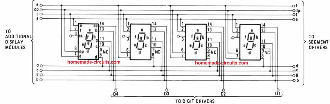
To quickly test the working of the 10 MHz digital frequency counter circuit, apply a sample frequency which can be under 100 Hz. Put a momentary jumper to connect U1 pin7, 23, or 27 with the + 5V as advised through the dashed line displayed in the first circuit doagram. IC U1 after that implements the count for all digits greater than D2. Data for U2 signifies that C1 can be a trimmer or variable capacitor. Having said that, a 22 pF fixed disc capacitor can work reasonably well for the majority of applications, and offers precision to .005 %.
Begin by setting the range switch to "1 second", implement the multiplexing frequency from U2 pin 12 to the input of U3, and fine-tune the trimmer to get a reading of 1280 Hz.
Measuring Frequency
When S1 is positioned at the 1- second mode, the count range is between 1 Hz to 1 MHz, which will provide a direct reading from the display. If S1 is moved to the 0.1- second position, the measurement range increases to 10 Hz to 10 MHz. The figures as a result showing up on the display is 1/10the of the frequency that is being measured (1 kHz appears as 100).
In case you try to measure a new frequency, the first reading will turn into previous frequency which was latched in the counters.
You will have to wait for 2 or higher count intervals for the circuit to stabilize around the newly applied frequency.
Alternatively you can try pressing the RESET switch (S2) until the display shows "00," and then you can release the switch.


Comments
Can this circuit be modified to measure time intervals.