An all-in-one automatic voltage battery charger circuit is discussed in the following post; the circuit can be modified in many different ways as per individual requirements and applications.
The following circuit will allow you to charge any battery right from 1.5V to 24V simply by setting up a given preset.
How it Works using LM3915 IC
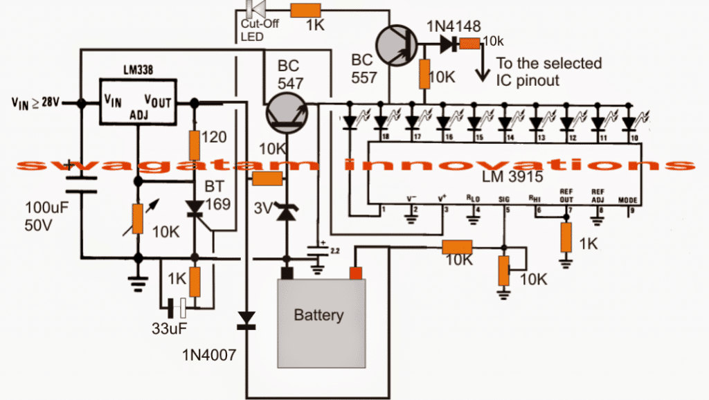
The circuit functioning may be understood with the following points: The IC LM3915 which is a Dot/Bar voltage display chip forms the main section of the circuit.
The IC has ten linearly incrementing output which sequence one after the other in response to a rising potential fed at its pin#5. Thus the output sequence corresponds to the instantaneous voltage level at the "signal input" pin out of the IC.
The 10K preset associated with the above IC is set as per the battery voltage which needs to be charged. After this the LEds connected at the output linearly indicate the charge level of the battery by illuminating in sequence, and finally when the last LED is lit which happens when the battery gets fully charged, the SCR is triggered shutting off the charging process permanently until the power is reset.
The stage comprising the IC LM338 is a standard voltage regulator IC, the preset associated with IC is set as per the required full charge limit of the connected battery. The transistor BC547 provides a fixed 3V for the connected LEDs for controlling the IC dissipation.
The transistor BC557 remains switched OFF as long as the last LED in the array which may be selected for the full charge indication is not illuminated. As soon as the last "full charge" LED switches ON, the BC557 is also switched ON triggering the SCR.
The SCR instantly grounds ADJ pin of the LM338 completely disabling the IC and the output to the battery. The battery now stops receiving any voltage and thus it is inhibited from getting over charged.
How to Set Up this Circuit
The circuit can be used for charging 1.5V, 3V, 6V, 9V, 12V, 15V, 18V, 21V and 24V batteries, in fact any voltage that may lie between 1 and 24V. Suppose you want to charge a 6V battery, the full charge level for this battery would be 7V.
The setting of the circuit may be done in the following manner:
- Do not connect the battery initially and also keep the SCR gate disconnected from the BC557 network. Apply a relatively higher DC potential at the input of the IC LM338, may be a 9V or a 12V input.
- Adjust the 10K preset under the LM338 such that the battery terminal points receive a 7V output.
- Now adjust the 10K preset under the IC LM3915 such that the last LED just flickers ON at this voltage, meaning at the applied 7V.
- Restore the the SCR gate connection as per the circuit diagram. That's it the circuit is all set now.
- During the charging process each LED will correspond to 7/10 = 0.7 volts, meaning say at 5V the 7th LEd will be illuminated and with a rise of 0.7V the subsequent LED will be lit and the sequence will proceed from 7t to 8th to 9th and then finally to the 10th LEd shutting off the circuit and the charging of the battery.
Alternatively if you you are interested in making the circuit respond with all batteries from 3V to 12V then you may adjust the LM3915 preset such that the last LED barely illuminates at 14.4V.
Now each pinout of the IC corresponding to the relevant LED would sequence at the rate of 14.4/10 = 1.4V, therefore for a 6V battery the full charge LED pinout would be 7/1.4 = 5, meaning the 5th LED illuminated would indicate that the connected 6V battery is now fully charge.
For enabling automatic cut off for the above situation you just have make sure the base of the BC557 is connected to the 5th pinout of the IC LM3915 from left to right.
For a 9V battery it would 9/1.4 = 6.4th LEd, meaning when the 6th LED is fully glowing and the 7th LED is barely flickering, the 7th LEd may be selected and joined with BC557 base for acquiring the required automatic cut off.
Circuit Diagram
Using Transistor Latch instead of SCR
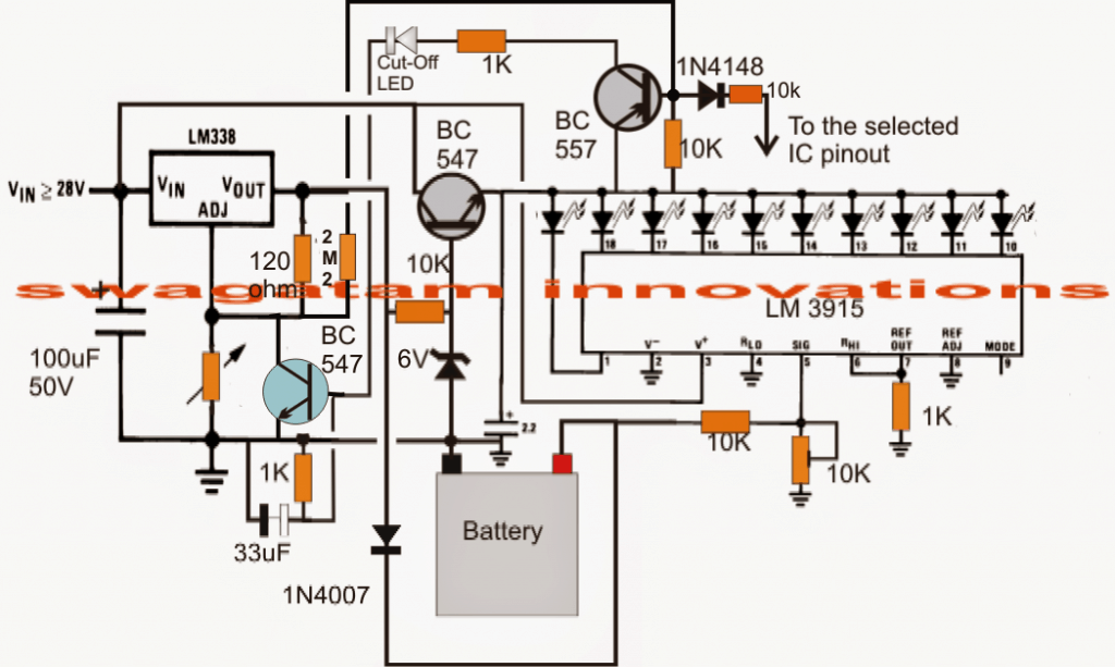
If the above circuit fails to respond with an SCR, the following circuit using a transistor latch can be employed:
For an Automatic ON/OFF Function
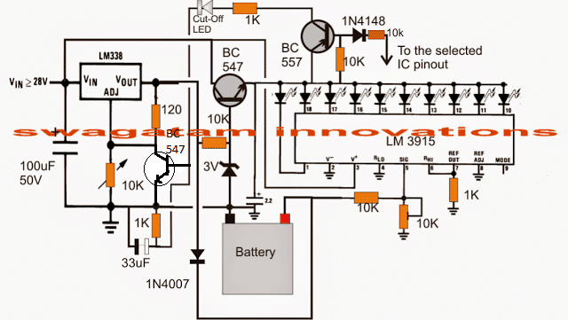
If you want the above multipurpose battery charger circuit to cut off the charger while the battery reaches the full change limit, and then quickly switch ON the charging when the battery starts dropping below the full charge limit, and continue flip flopping at this threshold level, in that case you can try modifying the design in the following manner:


Questions & Answers
Hi Sir,
I agree to your logic but it will take long time , without removing any cap I got a suggestion if we connect an npn transistor base to the base of bc557through a resistor when ever the positive voltage appear fr the ic the transistor will trigger and the ce of tr will get shorted, if we open the cathode connection of scr to ground and connect the c to cathode of scr and the emitter to ground the problem is solved .We can also use this transistor to switch on a small relay and use its contacts in between the scr cathode and ground.
Regards V.Sambath Kumar.
Thank you Sambath,
what you are saying is possible, but it requires extra parts and effort.
Using an unfiltered DC at the input solves this problem in an easier way, and can in fact promote desulphation of the battery and enhance battery life.
Hi Sir,
In the scr version we get a positive voltage through theCE of bc557 to trigger scr to stop the charging , scr once triggred the anode to cathode remains permanently shorted until either cathode or anode is dis connected from the circuit so how do you switch on the charger when the battery voltage come low again.
Regards V.Sambath kumar.
Hi Sambath,
Yes, that’s right, the SCR will get permanently latched and won’t respond when the battery voltage drops to lower level.
To eliminate this issue, you can remove any filter capacitor associated with the input DC, so that the DC after the bridge rectifier comes with a 100 Hz ripple.
Just make sure to connect a 10u/25V across the base/emitter of the BC557 transistor.
Student I want to learn
Using the IC LM338 I needed an indicator at the output that will indicate the battery ???? is fully charged..
Where can I do that on the circuit.?
You can simply connect the following circuit across your battery terminals for showing the full charge:
https://www.homemade-circuits.com/battery-full-charge-indicator-circuit/
OK can I get the full PDF form of this work??
You can easily convert it pdf using any online “URL to pdf converter”
Hello Mr. Swagatan, I need some help with the first lithium-ion battery charger. I’m a hobbyist who enjoys building projects from schematics. I put together the charger on a breadboard but somehow I’m not able to figure out how the potentiometer near the LM338 Var. Regulator is to be wired in. I don’t get the right variable voltages at the battery terminals and I get feed back lighting up the LED’s. After many attempts at retracing my steps I still am unable to make this work. Nothing gets warm and it hasn’t blown any fuses. I need this for charging 9v batteries. Thank you, Ed
Hello Ed,
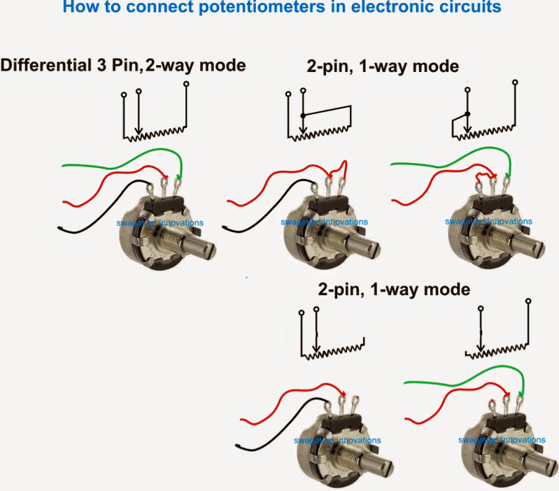
You must use two terminals of the potentiometers for the connections, the center terminal and any one of the output terminals.
An example image of the pot connections can be seen below:
Please see the “2-pin 1 way mode”, you can use any one of those methods.
Make sure not to connect a battery while adjusting the LM338 output voltage. Adjust the voltage by connecting a meter across the points where the battery is supposed to be connected.
Connect the battery only once the pot adjustment is completed and the voltage is correctly set.
Also, make sure that the collector link of the BC557 transistor remains disconnected while the voltage adjustments is being done. Restore the connections once the voltage adjustment has been completed.
Nice circuit diagram
24v battry chager transformer calqultion data
Hi, Greetings dear Swagatan, how are you? The circuit is very interesting, but the LM3915 is difficult for me to find. Could you suggest a circuit with similar functions: to charge 3V, 4,5V, 6V, 9V, 12V batteries, but using IC LM 7805 or any of the LM78xx series? A Yotta of thanks, Joakin
Hi Joakin, There’s no replacement for LM3915. Instead you can build a variable power supply unit using transistors or an IC LM338 which can be adjusted to suit any battery voltage.
https://www.homemade-circuits.com/how-to-make-current-controlled-12-volt/
Hi, thank so much for your answer,
Dear Swagatan the LM3915, can not be replaced by LM3914?.
In my letter I do not ask to replace the ic lm3915, but to make a circuit that does the same function, but uses LM78xx. Tell me a way to send you the circuit, cause this way i dont see how to do that. Thank you. Joakín
Hello Joakin, yes LM3915 and LM3914 are two versions of the same IC and are interchangeable.
It can replicated by using 10 separate op amps, as found inside the LM3915 IC:
You can upload your circuit to your Google drive and send me the link here, I will check out the circuit.
make sure to remove the https from the link.
Good morning Swagatam, hope you are well,
In the charging circuit with automatic ON/Off function there are 3 capacitors, 1 = 100mF, 50V, 1 = 33mF and 1 just above the battery of 2,2mF. (dwg which I downloaded not very clear) What the voltages be on the last 2 caps?
Another issue is all of electronic suppliers locally tells me – No stock of the LM3915 IC, what now? What other IC can I use?
Best regards,
Marius
Good Morning Marius,
the rule of thumb is that the capacitor voltage must be 1.5 times or 2 times the supply voltage. So if the supply voltage is 12V then the capacitor minimum voltage can be 20 V or 25V, or any higher value.
LM3915 is a pretty standard IC, so it is strange if it’s not available in your area, nevertheless you can always order them through any online electronic stores or through Amazon and eBay.
Unfortunately there’s no replacement for this IC, unless external op amps are configured to implement the same job….
Thank you very much for your valuable reply, will have to go your recommended route
God bless
I am glad to help!
Hello Swagatam,
Pls can this your circuit charge lithium batteries or they are for lead acid batteries?
Thanks for your response.
Regards
Ebai
Hello Richard, you can use the concept for Li-ion battery also, just make sure to use an input current that’s 50% of the mAH rating of the battery.
Dear Sir,
I want to charge 4 mobile phones using a 12v motorcycle battery.What should I do?
What is the circuit diagram?
Please help me.
Thank You
Hello Praveen, you can try the 5) LM338 based design from the following article:
https://www.homemade-circuits.com/how-to-make-simple-dc-to-dc-cell-phone/
Since motorcycle battery gives a DC current, How should I changed the above circuit??
You can eliminate the transformer and the bridge, and modify the circuit in the following manner:
Dear mr Swagatam,
Possible to make automatic battery charger 12v 24v 200ah diagram using pulse/ferrit (EE35/PQ3230) transformer for saving cost to made it
GBU
Thanks and regards
St
Dear Salim, I do not have a 20 amp SMPS design, and it would be a pretty complex design for sure, better to get one readymade
Dear Mr. Swagatam, No need rewinding coil SMPS, just make from SMPS ready to use (EE35/PQ3230), most of them many and easy to find in the online marketplace ☺️
OK, thanks for the feedback!
DEAR MR SWAGATAN DO YOU HAVE A SIMPLE TRANSISTOR CIRCUIT 12V 50A- 80AMP CHARGER THAT HAS AN AUTO CUT OFF WHEN BATTERY IS FULL
Hello Jemithias, You can refer to the following articles. You may find them useful:
https://www.homemade-circuits.com/simplest-smf-automotive-battery-charger/
https://www.homemade-circuits.com/self-regulating-lead-acid-battery/
Hi Mr. Swagatam, I found this circuit of great interest. My need for charging is: During long driving hours, during holiday periods, in my vehicle my wheelchair can be fully charged. In my vehicle I have provided 12 volt 30 amp cable (8mm2), to place the wheelchair is located. The wheelchair has AGM 12 volt 70A X2, series connected to 24 volts.
I have found a Step up converter, max 15A in / 440 watts, where I have to convert 12 volt voltage in the vehicle up to approximately 27 volts which is applied over the LM338K input (TO3 ver.) I would use technical form 3, For an automatic ON / OFF function
1. LM338 can deliver 5A max, how can I connect 2pcs LM338 in parallel that can provide up to 10A charging current and drastically reduce the charging time? I have read that the adj. line LM338 connected in parallel must be checked to be exactly the same / identical, for example with the use of an op.amp ic which controls the voltage on the output line. I found such a connection, but it may indicate it would be difficult to fit into diagram # 3. https://1drv.ms/u/s!AizwNFNuGCzdtIxNDWUJJql4ORm_nw?e=nhn7wJ Do you have another better idea/solution to gain up charge current?
You have a nice calculation technique for the LM3915, as follows: “Alternatively, if you are interested in getting the circuit to respond with all batteries from 3V to 12V, you can adjust the LM3915 preset so that the last LED light barely lights up at 14.4 V.
Now each pinout of IC corresponding to the current LED sequence at a speed of 14.4 / 10 = 1.4V, therefore for a 6V battery the LED pinout with full charge would be 7 / 1.4 = 5, which means that the fifth LED will indicate that the connected 6V battery is now fully charged. ”
But how does this work out for 2pcs 12 volt AGM batteries in series (24 volts)? Here I should connect BASE to BC557 / PNP to LED furthest to the RIGHT, when output voltage is regulated under LM338 to around 27.5 volts?
Thank you for your incredible and extremely good electronics guide pages.
Hi again, Swagatam , and thank for you feeback, a support joy you show me, I will share with you.
I now made a new diagram for this 3v, 4.5v, 6v, 9v, 12v, 24v, automatic charger. Since I now wanted a doubling of the charging current, 5 amps up to 10 A, some change of the schematic diagram was necessary. I now removed the cut of transistor in the adjust inputs of my two LM338, and replaced this control performed by an Op amp. UA741. The emitter output in the attached diagram (Q4) now controls the regulator for the LM338 voltage level. Two 0.3ohm / 10W resistors are mounted in the outputs of the LM338. Note LED1, marked with a red circle, cut off voltage at measured charging voltage, 27.5 volts in my project, is this connected to the correct side, inverted / not inverted side of Op amp.?
Thank you so much for the response, a support that makes it a pleasure to spend my free time with electronic building projects!
Se my new diagram (with a fan speed controller (LM358) to a fan mounted at LM338 cool radiator ribs)):
https://drive.google.com/file/d/1BcWFbQ4H9nvMQs__i-Ixc0oCYdoVJD96/view?usp=sharing
Thank you Anderson, I appreciate your interest and efforts, however it seems the link you have sent was not set to the shared mode, and therefore it isn’t opening at my end. After referring to the diagram I should be able to provide you with my opinion.
Thank you Mr.T.Andersson, I appreciate your interest and curiosity regarding the concepts explained above.
To get 10 amp output you can connect two LM338 pins in parallel with a common regulator circuit, and also make sure to mount the two ICs over a common heatsink so that they can share the dissipation uniformly.
Yes, for a 12 V battery the 5th LED will correspond to 7V and so forth.
For a 24V battery the 5th LED will correspond to 14 V, but the indication range will keep getting squeezed more and more as the battery source voltage increases. Yes you will have to depend on the furthest LED (10th) for the full charge cut off(28V), and for the BC557 base integration.
Mr. Swagatam and I’ve seen those tutorials from different sources and battery chargers and I’m very interested in those topics because I work with electronics, maybe not very advanced but I understand a little of the basics but I don’t know if my question is related to what in this This page is commented but I have always wanted to make a my good battery charger but also annelo to make a My little welding machine I think that maybe that is another issue but I wish if you were so kind to guide me in this regard, notice that I have 2 toroidal transformers, it is 20 centimeters diameter by 7 high I do not know if you could guide me if I can join the 2 primaries and remove the secondary of the two and make a single one for the output and if possible, what gauge of wire would be used or any guidance that will give me I am grateful in advance for yourattention I hope you can read my writing I will be waiting for any suggestion a thousand thanks in advance
Hello Edgar, designing or amending transformers require critical calculations, and cannot be judged through assumptions. So I am sorry it won’t be possible for me to suggest regarding the transformer winding that you have asked.
Hi Swagtam, i want to charge my 3 lion battery connected in series with a 12 volt 2 amp charger. I dont want to display the full led indicator for battery capacity. Only i want to automatic charge and cutoff when fully charge without a relay. Pls give me solution. Also i want to charge a 3.7 volt single cell lion battery also. Pls give solution.
Hi chandrashekhar, you can use the second last concept from this article:
https://www.homemade-circuits.com/usb-automatic-li-ion-battery-charger/
use 12V as the input instead of the shown 5V, and set the preset for the desired level cut off
Hello Mr. Swagatam.
I have been following you for a long time. I need your help. I have a 14.8v, 2.1Ah, 31.1Wh lithium-Ion battery. To charge this battery, I have to design a circuit with automatic charge cut and charge status indicator(with led). Which is the most suitable circuit for me in this regard. Can you help me? Thank you for your interest. See you.
Respects.
Hello, Mr. Sw.
Thank you very much for your interest. I do not want to use the relay
in the circuit. Can you suggest another circuit that I can use instead?
Noble, Then you can try the other circuit which is without relay in the same article…second last one may be
Thanks Noble, you can try the last circuit from this article:
https://www.homemade-circuits.com/usb-automatic-li-ion-battery-charger/
Replace the relay with a 12V relay.
Replace the transistor base resistor with 10K
Use a 16V input with 1 amp current.
SET the preset to get a precise 14.8V cut.
Hi Swagatam,
i like your posts. i am having littlebit knowledge of electronics.
i have 24V 2A smps power supply.
1) can i use this power supply as a battery charger to charge 12volt 100ah battery
2) what circuit is required additinally.
t&R
Prashant
Thanks Prashant, you can use a buck conveter to convert 24V 2 amp to 14V/ 3.5 amps, but this current can be too low to charge a 100 Ah battery, as it will need minimum 8 to 10 amps for optimal charging within 12 hours
hi,
thanks for your reply,
it is possible with this ps obtain higher current? or required new transformer with rating 24-0-24v 10amp
Transformer rating will need to be increased. The ideal transformer would be a 12V 10 amps which will become 16V 10 amp after rectification
i think this is a pretty cool website im glad i stumbled opon it , ok my question ,wich i will have many more on other projects later on , but for now i was wondering ,i am disabled and dont have much money but i do have a pile of electronic equip of variouse brands and type ,is there cirtain items that may have the same parts you listed that i could break into and reuse i am very resourcefull and i love to make tools and such from old electronic equip.
Glad you are enjoying the posts. Yes you can salvage most of the passive parts except the ICs
sir can i use this circuit for 12v 50watt solar panel to charge 12v 35ah lead acid battery ? and is it auto cut-off? & auto charging?
Abhishek, yes you can but a 12V panel will not charge a 12V battery. The panel must be rated at least at 18V
Hi,
I am a novice in electronics, so here is the question?
Using this circuit I would like to charge 3V NiMH batteries of various currents
@ 3V charge voltage what would be the charging output current of this design?
I am trying to charge 3V batteries with automatic cutoff but trying to do it reasonably fast
Thanks
Vas
Hi, you can replace 1N4007 diode in series with the battery positive with an emitter follower stage. Use a 2N2222 transistor, connect collector to the output LM338 or LM317, connect emitter to the battery positive. Connect the base with collector via a 1K resistor, connect the base to ground via a 10K preset. Adjust the LM338 out to 6V, adjust the base preset to get 3V at the emitter of the 2N2222
Thank you Sir
I think I get it will try to adjust the circuit and see how I get on
Will come back if stuck
Much appreciate the support
Vas
Thank you Vasilis, Actually all these are not required because the LM317 or LM338 output itself can be reduced to 3V easily, I just forgot about it…
Thank you
Any idea what would be the power/current output @ 3V for this circuit?
The power consumption will depend on the battery specs, and will need to be set accordingly through a series resistor or simply by using an appropriately rated power supply.
Sir I have designed the circuit and am facing a few problems…please may I get your contact details
Aditya, you can feel free to discuss your problem here through comments, I’ll try to solve it for you!
Sir I’m from the Indian naval academy and its difficult for me to access the internet..i request you to please share your contact details
I am really sorry Aditya, personal contact may not be possible, I can solve your queries only through this platform!
Sir the powe supply from external source and the battery positive both are at pin 5..in such a case the display circuit should not function as expected
Aditya, yes that’s right, the external voltage should drop to the discharge level of the battery and this data must reach pin5 of the IC through the potential divider network…make sure the source current is significantly lower than the battery Ah value.
For what kind of accumulators is intended the charger presented? It will be appropriate for Ni-Mh accumulators, which charge at constant current?
It can be used for all types of batteries but with appropriate current control setting.
If you want to charge a single battery with fixed voltage then I wouldn’t recommend this complicated circuit, there are much easier circuit present in this website
I want to thank you, Mr. (or Sir, i don’t speak english very good) Swagatam, for your amability to patientely answer my questions in such a short time. I’m from Romania and i’m glad to have had the privillege to benefit from your experience of electronic engineer and to meet you, even in this manner, by comunicating through the internet. Also, i wish you all the best, personaly and proffesionaly. I will manufacture the circuit, and hopely it will work.
Best regards,
Mihai
Thank you Mihai, I am glad I could help you! The circuit surely work, let me know if you have any problems while testing it.
Hello, Mr. Swagatam, i would like to use the charger to charge a 8.4 V Ni-Mh accumulator, 280mAh. Should i use that charger or other? How could i set the current to battery to 1/10 of capacity (28mA) ? Thank you!
Hello Mihai,
I think you should use the following circuit for your battery:
https://www.homemade-circuits.com/usb-automatic-li-ion-battery-charger/
you can use 50% current rate for the charging, meaning at 150 mAh if you want a fast charging, but lower than this will be safer, so probabaly 100 mA will be OK.
Set Rx to = 0.6 / 0.1 = 6 ohm, 1/4 watt
And the charging imput for this type of accumulator? Which should be it’s value?
Charging voltage should read 10.1V across the IC supply lines. The polarity protection diode may drop 0.7V, so adjust the input according to this drop.
Mr. Swagatam, i forgot to mention i’m a begginer in electronics, so i need more specifications. One of my question is that will be all right for the charging input to be 11.2 V, the appropriate voltage for completely charging 8.4v accumulators? This voltage won’t destroy any of the components in the circuitry? And what should be the preset voltage for that type of accumulator (10.2 will be suitable, but won’t charge it completely?)
Another question is about the method of detecting the charge state of the accumulator. I read on the internet that for a Ni-Mh accumulator, the voltage across it is not a precise indicator of it’s state of charge, or the circut doesn’t works by this method?
And another question, i found on the internet the next schematic:
https://www.shdesigns.org/pdf/lionchg2.pdf
I built it and charged the accumulator at the preset voltage of 11.2 V, but i stopped the charging process manually when the voltage across it reached 10.1 V. I would like the charging to stop automaticly, but what would be the preset voltage? The two schematics are based on the same principle? I don’t really know if the schematic you recomanded me is better, and if so, please explain me why.
Thank you.
Hello Mihai, I think your battery full charge level is 8.4V, and the printed value is 7.4V (3.7 + 3.7 = 7.4)….So make sure your battery does not charge over 8.4V, otherwise it can get damaged. The schematic that you have shown will not cut off at the full charge which can be dangerous for the battery, so I won’t recommend it. The circuit given by me will cut off automatically at the preset level which should be 8.4V.
The schematic given in the article is more correct, so you can build as per this diagram
Sorry, I just forgot your battery is Ni-Cd, I mistakenly imagined it to be a Li-Ion…so it can be 8.4V. The full charge cut off level should be 10.1 V as mentioned by you.
sir we aim to design a project to charge batteries of various voltages,indicating the level to which the battery charges and also cutoff the battery from the circuit once the battery fully charges.
we would be pleased to have your correspondance details
Hello Aditya, please specify the range of the battery specifications, and the features the charger is supposed to have, I’ll try to help!
Hi i had a catamaran very old is a project it have 2 dc motors 144 volts and a battery bank it suppose to work with solar panels an a gas generator and i would like to had a battery charger for that voltage changing some values on this thanks my e mail is yudando ayudandoalmesias@gmail.com thank2
Hi, please specify battery bank voltage, current, and solar panel voltage, current, I’ll try to help!
Hello sir, please I need the circuit diagram of a 24V, 200AH battery charger and a charge controller
Hello John,
You can try the second circuit from the following article:
https://www.homemade-circuits.com/make-this-48v-automatic-battery-charger/
Hi, my name is Su-Hong Jeong and I live in Korea. I’m trying to make a battery charge tester, and the battery is 1.5V, (AA battery). And I’m going to use either Lm3914 or Lm3915 to check the remaining amount through a bar LED.In addition, I don’t want to use transistors. I sent you an e-mail to see if we could get a circuit diagram and put my e-mail address on the bottom. Please reply
wjdtnghd12@nate.com
Hi, you can use the second circuit from the following article;
https://www.homemade-circuits.com/lm3915-ic-datasheet-pinout-application-circuits/
You can connect the 1.5V supply across pin#5 and ground.
Hi dear! first of all i wish you a long live not only for your innovations but also for your humble/kindness humanity. by the time i go through your blogs you are answering all questions raised from your followers with out tiring and getting bored and this is what makes me amazing regarding you. I,’ m from Ethiopia and follower of you.
It’s my pleasure Habtanu, please keep up the good work! Wish you all the best!
Can i use this circuit to charge a 12v 200ah battery or should i make some mods
No it won’t be possible, unless you upgrade the LM338 with an outboard transistor so that it is able to handle upto 20 amps
Hello sir, i used lm317 instead of lm338,
1. if i want to add transistor 5A to it, in order to increase the current, will affect the 120 ohm resistor, or do i hav to change the value.
2. If i connect the input of the regulator to the collector of the transistor, the output to the base, then the emmiter should now be the output, so my question is, from ur diagram, should i disconect the end pin of 120 ohm resistor and the diode anode at the output of the regulator, and reconnect them back to the emmiter (the new output) of the transistor? Hope my questions are clear. Pls help. Thanks
Solomon,
If you connect the transistor in the mentioned manner in that case it will need to be done as shown in the following article
blog/high-current-lm317-variable-power-supply-circuit/
Greeting to u sir. Pls help me out.
1. Can i use 3.9v zener diode instead of 3v?
2. Is there any effect for higher or lower voltage zener diode in the circuit?
3. Where should the middle of the 10k preset in adj pin of lm338 be connected
1) 3.9V zener will do.
2) Any zener below 6V can be used.
3) you can use the middle lead, and any one of the outer leads of the pot, the third one can be left open or unconnected.
Sir, but the other outer lead is grounded
It is just a symbol, you can either use two pins of the pot (center pin compulsory), or short the center one with the unused pin, and still you get two pins for connecting…
Hello sir i need your help still on this circuit, i want to use TIP127 to increase the amperage of the circuit, of which told you early i want to use lm317 instead of lm338. According to the data sheet of lm317, it current is 1.5A, of which is not enough to charge my 50AH battery, I want to increase the current using TIP127 transistor, and according to the datasheet of the transistor, its current is 5A, of which you told me earlier the output current equals ic’s current plus transistor’s current, which is 1.5+5=6.5A, which not recomended for charging 50AH battery. Now my question is, i want the output to be 5A, can i limit the 6.5A with a resistor using ohms law? Or is there any alternative to reduce the current? Pls help. Thanks.
Hi Solomon, the ideal charging rate for any lead acid battery is 1/10th of its Ah level, but this not entirely critical, if you are using 6.5Ah that’s only marginally more, so no problem you can go ahead with 6.5Ah and still charge your battery safely.
Ok sir, thank u
Still talking about the last diagram sir, now it means the BC547 near the voltage regulator serve as the cutoff region to replace the scr?
2. Can i apply same design(the retarting function) to the first circuit containing the scr?
3. The capacitor at negative terminal of battery is it 2.2uf or 22uf. Thanks.
1) SCR will latch ON permanently once triggered, so it cannot be used like the last circuit.
2) It is 2.2uF but it can be any value, it is not too critical.
I appreciate and more grateful sir, more strength to ur elbow, keep it up. Thanks
Thank u sir, i may understand u right, u meant the two output pins connected together to the base of BC557 one for desired full function(say pin 10 for 14.4v full charged ) and the other one for the restarting function(say pin 8 for 11.6 or 11.4). Pls correct me if wrong. Thanks
yes that’s correct.
since each pinout for a 12V battery would correspond to 1.2V, two of them would enable 2.4V difference, so last two pins will mean the battery getting cut off at 14V, and restarting at 14 – 2.4 = 11.6V
Wow thank u very much sir, u are great. I will implement the circuit.
You are welcome!!
I meant as inverter having battery input wires, red and black out from the inverter’s frame, if now i want to charge the battery of the inverter, i must connect the battery through external charger. My question now is, instead of connecting the charger externally, can i transfer the charger inside the inverter’s frame and then connect the charger’s output directly to the battery terminal inside the inverter’s frame? Can it be posible?
yes you can do that, no need to isolate the battery from the inverter, just make sure the inverter is not turned ON while the battery is charging, or until the battery is fully charged
Ok, i now understood, thank u sir.
Hello sir, for this article, in the last circuit diagram,
1. what addition makes it to automatic start charging when the battery is below threshold?
2. Can i use the first circuit with scr to do same function as the last?
Hello Solomon, that can be done by selecting 2 pins together instead of 1 from the LM3915 outputs and connect them together with the BC557 base. This will add the required hysteresis to the design, and will allow you to switch it back only when the desired lower threshold is reached,….meaning after the activation of the 2 pins have elapsed, which may be equivalent say 1.2V into 2V = 2.4V,
so 14V – 2.4V = 11.6, so it restarts back at say 11.6V
Hello sir, i have general questions to ask u pls help me with the answers.
1. I have inverter circuit, automatic cooling fan circuit, mains AC overload protection circuit, all operating with 12v voltage source(battery), is possible to join all their positive terminals on one place and all their grounds on one place on my circuit?
2. I want to put battery charger circuit together with inverter circuit in one case, to make the charger in-built such that the charger’s output will be connected to the battery terminal of the oscillator’s circuit, can it be possible? Or will the charger circuit cause an effect the oscillator circuit?. Hope my questions are clear, pls help. Thanks.
Hello Solomon,
your first point is possible, you can join all the 12V positives together and same for the ground line.
The second point is not so clear, a schematic will be needed to answer it correctly
Hello sir, i have a little problem with this circuit, LM338 is not available in my area, i have another alternative which you will help me comfirm and modify. You posted one circuit in blog,’317 outboard current boast’, i want use the circuit to increase the current output instead of using the ic, and also i want to use TIP127 for current, help me to modify the circuit. If it can simply explanable, eplain to me, if it is a little bit complex, please disign the modified circuit and send it to my email(solomonanthonyamtunawa@gmail.com) . Pls help sir, thanks.
Hi Solomon,
I have replied to this question which was asked under LM317 current boost article
Hello sir, pls i need a little modification for this circuit, i want to attach a buzer that will make an alarm when battery is low, pls help me to modify it. Thanks
Hello Solomon, just confirm the pinout which is supposed to activate at the assigned low threshold level, and connect the piezo buzzer across this pin and the positive supply terminal
Hello sir, can i use 18v solar panel as the voltage input?
yes you can use it, but first confirm the set up with a normal power supply
hello sir, pls i have few questions to ask
1. can i use LM3914 instead of LM3915?
2 where should i connect the other pin of the 10k that is not connected?
3 will the LM3915 monitor the battery voltage even when it is not charging? if no, i need modification pls. thanks.
Solomon,
you can use LM3914 instead of LM3915.
I have already explained elaborately regarding the connection of the 10K resistor or the base of BC557 with LM3915 pinouts, please read the article in detail and build it only if you have understood the circuit well, otherwise you may fail to succeed.
yes the LM31915 will continue to monitor since it is directly connected with the battery supply
can I use an other SCR? like bt151?
you can use any SCR, but BT151 is rated at over 1 amp which is not required, it just needs to be 100mA
hello sir i have got a tip142 rated at 100v
collector current current ic 10amp. now wil i need to add a resistor. thanks
Olupot, TIP142 is NPN, you can try TIP147.
you will need resistors as per the explanation provided in my previously referred link.
hello sir thanks alot i appreciate the good work you do.
i want to ask alittle you said that if one wants to charge batts above 50Ah he should think of adding a transistor say TIP. so where can i place it and which rating if am charging batts between 100Ah to 200Ah thanks
Hello Olupot, the LM338 can handle a max current of 5 amps, therefore for applications above 5 amp the LM338 can be reinforced with an outboard transistor across its output and input terminals, as shown in this example design:
makingcircuits(dot)com/blog/7812-7805-ic-current-booster-circuit/
hello sir i was reading the data sheet of the ic lm3915 which you used but i got one interesting thing about it that you can use a vacuum flouresent display or liquid crystal display.so i would you to try and replace these leds with the vfd or lcd i know can thanks alot
Thanks olupot, actually that will not show a numerical display, rather only a digital bar graph display, I have shown LEDs in the above circuit because LEDs are easier to procure and connect.
Sir, I have 4 volt 1 Ah rechargable lead acid battery.Hence it should be charged with 100mA current.how can i reduce current to 100 mA keeping voltage constant.I have varible DC power source or can i use 5v cell phone charger
Saurabh, you can use your mobile charger for charging the mentioned battery.
Just make sure to connect a resistor in series with the positive of the battery, the value may be calculated with the help of Ohms law as given below:
5 – 4 / 0.1 = 10 ohms
watts = 1 x 0.1 = 0.1 watts…1/4 watt will do the job.
Where is the place that we should place the variable 10k resistor? Just before the IC or other place you have figured?
use the middle pin and the any one of the outer pins, leave the outer pin unconnected…
Its mean near the voltage regulator? if it so where do we want to connect the middle pin of the variable resistor?
the positions are clearly shown in the diagram…
how to create a emergency light over charging breaker
Sir
i want to make a light, with rechargeable battery, battery charging keep plug in with over charging breaker.
i want to make 1W lED turn stay on.
if AC available on AC, if no AC it shifted to DC battery and battery get charge but cut off when fully charge.
what exactly are you tying to make? please specify in detail.
yes LED will turn OFF in the presence of AC mains….
you can try the following design
https://www.homemade-circuits.com/2014/04/li-ion-emergency-light-circuit-with.html
sir,
i have 1 w Led and 4 v 0.8 ah battery.
what i want is a light on a battery so that if there is no ac to charge battery light works for atleast 2 hrs. and when ac light is there battery charge and it stop charging when fully charged.
Za, please specify the voltage and AH rating of the battery, I'll try to suggest
I am making a circuit using a Arduino and a servo to lift a lid with mechanical arm. I will be using a 9 V rechargeable battery ran thru a voltage regulator to get the 5 volts needed for the Arduino. My question is what kind of circuit would I need to add to place a solar panel to keep the battery charged properly.
Thank you sir
you can use a 15V panel and connect it directly with the battery terminals…the current of the panel can be around 7 to 8 times less than the battery AH rating
Hi sir,
I didn't find that schematic.
its showing error that "no posts available for your search"
here it is
https://www.homemade-circuits.com/2015/08/lipo-battery-balance-charger-circuit.html
Hi sir,
I need a balanced charger.
Hi Anu, please find it using the search box on top…..It is already posted in this website
Hi sir,
please help me to built a schematic for lithium polymer charging and protection circuit with voltage 3.7v and charging current 65mAh
Hi Anu, what kind of charger do you prefer, the ordinary type or balanced charger, because for automatic operation a Lipo batt will require a balanced charger.
A 1 watt LED will burn if you do not mount it over a heatsink, and also preferably add a resistor in series with its lead, for 4V input you could add a 2 ohm 1 watt resistor.
I am not sure about the motor, because normally a motor will never burn unless the input voltage exceeds the motor's rated value
hi SWAGATAM is it safe to use that circuit to charge lithium polmer batteries
yes it is safe, just make sure the input current is below 50% of the battery mAH rating
Hi,
sir i want to make a Transformer for my 24 volt battery,
i need 10 amp charging for my 24 volt battery can you please send me the number of Primary and Secoundry turns…?
Input Voltage is 220
and i need 10 amp for my 24 volt battery.
Thanks
Hi Sir, I am here again.. I try prototyping the 6V,12V,24V battery charger circuit as u suggested. But unfortunately, I failed and don't know where is the error within my circuit. So according to my requirement which is
1. The input voltage supply is from 3-27 V and the current is also variable for different batteries to charge
2. The circuit has an auto cut off feature when the battery is fully charged
Can i use this circuit to try on my project for the second time again ?
Hi Chaw, the previous design was much simpler and easily constructable, but if you could not succeed with it then your chances with the above is highly unlikely, as it's comparatively much difficult circuit.
first try to make a design fulfilling a single feature, could be the auto cut off feature and once you succeed with it then you could move ahead with the additional ones.
you can try this one instead
https://www.homemade-circuits.com/2012/07/make-6v-4ah-automatic-battery-charger.html
Hi Mr Swagatam,
I'm Mamdouh,
i need help, i have a circuit that conduct between 26-30 with adjustable 10k OHM amd draw 3 amps, how ever i need a circuit that can charge the battery and supply the system, in the same time when i connect an outside power source such as laptop adapter. also i would want an overcharge protection for my battery the battery im gonna use will be 22v with 6 amps. here's my email for better comunication, mamdouh.mikail@gmail.com. thank you very much.
Hi Mandouh,
you can use the following concept for your application
https://www.homemade-circuits.com/2015/10/smart-emergency-lamp-circuit-with.html
what is the current rating of the LED, the resistance value will depend on this….please specify it.
hello sir, i am feeling sorry because my english is not so good. i want to ask you which resistance is required to glow an led by a 4v battery having volts b/w 3.6 to 4.2 v otherwise when volts going low than 3.5 the led will off.
please sir reply answer of my question.
thanks a lot in advance
Show less
Hi KC,
I think the following design will be perfectly suitable for your requirement, you can try it:
https://www.homemade-circuits.com/2012/02/how-to-build-automatic-6-volt-12-volt.html
Can i just prototype it using breadboard also ? Plus, any settings needed to do like setting the coltage etc., before we charge a battery ?
yes that will do, the setting up procedure is explained in the article, please go through it thoroughly
Noted sir, thank u so much for your patience and clear explanation !! I cant wait to try my own one .. In the future, I will try to learn more from your experiments. Anyway, how can I contact you for any inquiry through your email or maybe others? Mine is kcsu97@gmail.com !! You really are a genius 😀
You are most welcome Chaw,
the best place to contact me is through the comments in my website, just as we are doing now. because I may miss an email, but I can miss a comment 🙂
best wishes to you…and feel free to discuss with me whenever you have doubts regarding any electronic concept.
sorry i meant to say
I may miss an email, but I can NEVER miss a comment 🙂
Thank you, sir . I really appreciate it !! Btw sorry for my incorrect usage there. Actually, it's not a rechargeable circuit. It is the circuit to charge battery by getting a DC power input to the circuit and output goes to different batteries to charge. I found the link u have provided is quite effective for me.
One more question is that in the diagram, i saw u are using 15-24V DC input. For my case, can I apply 0-12 V DC as they want it to be not more than 24V?
Regards,
Chaw
Hello Chaw, you can apply any voltage between 6 and 24V as the input for the referred circuit…0-12V will also work but only for charging batteries less than 10V
Hi Mr Swagatam,
I have done the modification as per my plan (which i mentioned in my previous comment above) the result is very good. The cut off is working well.
The charger that i have constructed has the following features:
1. One 10 positions selector to match the base pin of BC 557 with the relevant LED pin of LM 3915 for the full charged cut-off.
2. Two potentiometers. One potentiometer on the pin no 5 of LM 3915 is for setting the LED lighting for full charged cut-off. The other One on the adjustment pin of LM 317 is for adjusting the voltage of the charger output and cut-off voltage
3. One cut-off switch between the base of BC 547 and LED collector of BC 557. This is for the cut-off setting. With the charger in operation (power on), We will put the cut off switch in the position to cut the connection between base of BC 547 and the LED collector of BC 557. Then, we will turn the potentiometer of the adj pin of LM317 to set the cut-off voltage (ie. for charging 6V battery the cut-off voltage is 6.9V) and we will turn the potentiometer of pin no 5 of LM 3915 in such away that the LED of LM3915 will be lighting up at the targeted LED pin position when the full charge voltage is achieved (ie. the LED no 7 is light up when the full charge is achieved) Then, we will put the selector to the Relevant LED pin position of LM3915 ( to the pin of LED no 7). After that, we set the charger output voltage using potentiometer of the adj pin of LM317 ( this will be 7.3V), we then connect a discharged battery, and we turn on the cut-off switch (to connect the base of BC 547 to the LED collector of BC 557). By doing this, the charging process is started.
4. I installed a temperature triggered speed controlled fan to cool down the heat of the IC and power transistor
5. A dual V-Amp digital meter was installed
6. There are 5 LEDs on the front pannel. They are for power-on indicator, voltage regulator functioning indicator ( this LED will dim when the cut-off is happening or low output voltage of the charger is set or short circuit is happening), short circuit detection, full charged cut-off indicator and the last one is LED to indicate that the beeper circuit is in operation (this LED will be light up if the beeper circuit is in good condition and it will be flashing when the full charged achieved)
7. A beeper was installed to provide an audible full charged indicator.
8. The LED of LM 3915 is in the bar mode.
By now, i assume this poject is completed and i am going to utilize the charger to charge any size of battery (below 50AH) happily.
Thanks for your kind support.
See you on the next project…
Regards
Kanta…
Thanks Mr.Kant for your untiring efforts and determination, congrats to you.
I am sure other readers will benefit hugely from this.
Keep up the good work
Dear Mr. Swagatam,
What i am planning to do is, i will remove the 1K base/emitter resistor of BC 547, replace the faulty BC547 with 2N2222. Then, increase the value of base/emitter resistor of BC 557 from 10K to 100K in such a way that the Base/emitter voltage of BC557 become higher than 0.5V. Hopefully by doing this all transistors will be functioning properly. I will keep the collector LED of BC 557 as it is. Thanks
Regards
Kanta
Dar Kanta, that would be incorrect.
In the present set up the base of the BC547 is already getting 2.5V that is settling to the base/emitter FWD drop level of the transistor which is 0.5 to 0.7V…
simply check the voltage across the collector/base of the BC547….with BC557 ON, if this voltage shows zero then the BC547 is OK and conducting, and vice versa
Dear Mr Swagatam,
I did short cut the BC557 collector LED then i measured the base-emitter volatge of BC547, it was only 0.4-0.5 V. It seems that the BC547 is not properly triggerred, can i remove the base-emitter 1K resistor of BC 547? May this cause the low voltage of base-emitter of BC 547.
Thanks
kanta
Mr kanta, you can remove it but that is not relevant, I think your BC547 may be faulty….keep the LED connected, this LED will indicate whether the BC547 is conducting or not…you can also connect another LED in series with the collector of the BC547 for the confirmation
Hi Mr Swagatam
I jusr measured the BC557, using the positive as the basis, the base-emitter is 0.4 to 0.5V, collector-emitter is 0V. Hence, the BC557 is workingnormally. But, the BC 547 doesn't conduct. Can this indicate that the BC547 is mulfunction ?
Thanks
kanta
Hi Mr Kanta, if the collector LED of BC557 is illuminating then the BC547 may be OK, if not then there may be something wrong with the BC547 connections or the device itself….check the base voltage of BC547, if it shows 0.6V (with respect to ground) then it should be conducting…
or alternatively you may remove the BC557 collector LED and put it at the emitter of BC547, this will confirm the required results at once….
I am planning to replace BC 547 with 2N2222 in order to avoid any mulfunction again in the future since 2N2222 have higher current of colllector emitter.
You may do it, but it's not essential as long as the LMXX device is good…
Hi Mr Swagatam,
I forgot to tell you when the duplicate LM 338 was still functioning the voltage setting potentio meter got a bit warm. Now with LM 317, it doesn't get warm. Thanks
Regards
Kanta
If the pot is getting warmer then that's a clear indication of a malfunctioning LM338
Hi Mr Swagatam,
For your additonal information, the Cut off was wroking properly before the LM 338 got damaged.
Regards,
Kanta
hi Mr Swagatam,
Two days ago the 12V battery was charged completely, the final voltage of the charged battery reached 13Volt. The cut off was set to 14.4V. The Led on the pin 10 lighted up and lighted up also the led on the collector of BC557. But, the cut off did not conduct. When i checked the voltage were as follows:
On BC557:
Pin Base was 4.3V
Pin Emmitter was 4.8V
pin collector was 3.1V
On BC 547:
Pin Base was 0.6V
Pin collector was 13.6V
On LM 3915 led:
Pin 10 was 1.9 V
My opinion is, the BC 547 is not functioning properly or it might be damaged. this might be caused by the damaged LM338 (non genuine IC) in the past.
Please kindly advise.
Thanks
Regards
Kanta
Hi Kanta,
the circuit results indicate that except the LM338 stage rest all are working as proposed in the article, so that's better.
BC547 is also operating correctly, it's only LM338 which appears to be faulty.
However please note that all PNP device parameters must be measured with respect to the positive line , not the negative line….so for thee BC557 you should measure its base parameters with respect to its emitter which is associated with the relevant positive line
Hi Mt Swagatam,
The power to supply LM 3915 is 7815 and for the Led 7805. However, since the voltage from rectifier is 32V, if the 7805 connect directly to retifier, the voltage came out about 8V, last time. To overcome this problem, i then connected the 7805 to the output voltage of 7815. Since then, the output voltage of 7805 is 5 volt.
May i repeat the problem now is, the cut off beepper sounds but the cut off led remains off when the relevant pin of 3915 get activated.
Regards
Kanta
Hi Kanta, if you have used 7805 to supply the LED rail of the 3915 IC then the LEDs should definitely light up…I think you might have connected the LEDs wrongly or there could be some other fault with the LEDs.
Check the voltage across the LED positive rail and ground (negative).
BC557 base will be always have 0.6/0.7V and this value can never increase, if you try then the transistor will get damaged. And in this state the transistor will be in the activated mode…while with zero volt across its base/emtter it will be switched OFF.
the collector LED of BC557 must light up….because when the B557 is ON, current from the 3915 LED rail will enter the emitter of the BC557, come out from the collector, pass through the LED, enter the base of the BC547 and reach the ground through the emitter of the BC547…this must illuminate the LED.
Hi Mr Swagatam,
When the relevant pin of 3915 is active, the beeper that i installed is sounding, but the led doesn not light up. Then, i measure the emitter/base BC 557 voltage is 0.6V but the voltage of led is zero and also BAse/emitter BC 547 is zero. I am thinking it might be the 0.6v is not enough to activate BC557 since it requires minimum 0.7 V base/emitter. That is why the cut off led last time was dim come and gone hardly seen and cut off was not happening. Can you tell me how to make the base/emitter voltage of BC 557 become at least 0.7 V.
The Power to supplies the LM 3915 is using 7805 since the beginning.
Thanks
Regards
Kanta
Hi Mr Swagatam,
If i parallel the 2W resistor with the same value, the total wattage of resistor will become 6 watt, am i correct?
There is one thing that i forgot to mention is the cut off led does not lit. I measured the voltage of the base of BC 557, it keeps on varying from 0.7V then 0.6 then 0.8 then 0.6 etc. I remember last time when i charged the 6V battery, the led light was come and gone and the current to battery was still flown at 0.03 to 0.04Amp when the cut off voltage of 6.9 achieved. I dont know what is causing this. And now, the cut off led does not lit at all.
Thanks
Regards
Kanta
preferably use a 7805 IC instead of the BC547/zener stage which supplies power to the 3915 LEDs
..BC557 and the BC547 together form a latch circuit, make sure this latch is working….so that the collector LED of the BC557 holds and latches-on once its triggered.
Hi Mr. Kanta, first you will need to confirm the voltages across all the different points of the circuit, only then you would be be able to verify the actual working of the circuit, you can go through the other comments for more info.
The BC557 collector LED must light up, otherwise your circuit could be assumed to be not working.
BC557 base/emitter voltage will be 0 when the relevant pin of the IC3915 is not active (LED off)…if the relevant 3915 LEd is ON , only then the BC557 emitter/base would become 0.6V.
disintegrate the stages and check them separately, otherwise it will be difficult for you succeed with this design.
Hi Mr Swagatam,
Sorry, the transistor is MJ15023. I miss the first number.
Thanks
Regard,
Kanta
Hi Mr Swagatam,
i just finished testing the charger to charge 12V battery using your circuit of LM317 and outbound transistor with over current and shor circuit control. however, when i touched the Ry which is current control resistor, it is very hot. Is that normal?
I set the cut off to 14.4V, and charging voltage to 14.7 V. Once i connected the batery to charger, the V meter of the charger showed 13.3V and the current was 2.5A, then decreased to 2.2A, i think it is normal, right ? After testing for about 5 minutes, i turned the charger off, because i worried that the Ry (current control resistor) will get burned)
The resistor for activating the outboard transistor is 2.2 ohm 4W, because the minimum Veb to turn on the transistor of MJ 5023 is 2.2 volt, it is not hot. But, the series resistor (at the ground) for over current control is 0.167 ohm 6W (i connected 3 pieces of 0.5 ohm 2w by parallel) and this is very hot. Is that normal ?
The transistor is hot, but the LM317 is normal warm.
Thanks
Regards
Kanta
Hi Kanta,
yes it's normal, because Ry is restricting current therefore it can get a little hot. You can try increasing its wattage to control the heating.
the transistor emitter resistor and the Ry are the two resistors which are passing the actual current for the battery so if these become hot that means the charger is working normally.
LM317 is not becoming hot because the transistor is passing most of the current to the battery
I could not find the datasheet of MJ5023 so I am not able to verify its minimum base/emitter saturating voltage of it, 2.2V seems to be high, I don't think that may be correct.
Hi Mr Swagatam,
I am using the circuit no 2. the circuit with BC 547 replced the SCR which is in this link:
https://www.homemade-circuits.com/2013/08/3v-45v-6v-9v-12v-24v-automatic-battery.html
Thanks
Kanta
OK, got it thanks….
Hi Mr Swagatam,
Before i do modifiction on the circuit by using outboard transistor, i would like to ask you to kindly review on the circuit as follows:
1. The output from rectifier is arround 32V
2. A resistor of 1K/2W is put in between the rectifier positive output to V-in pin of LM317. This is to limit the current going to LM317 before the transistor turning on. Don't you think the resistor value is too high?
3. I use PNP MJ5023 transistor. The emitter is connected to the positive output of the rectifier.
4. A 1K/0.25W resistor is put in between the Base and the junction of the 1K/2W resistor and V-in pin of LM317.
5. The collector is connected to the V-out pin of LM317.
6. A 0.01 uF bypass ceramics disc capacitor is connected from the base to ground
7. A 0.01 uF bypass ceramics disc capacitor is connected from collector to ground.
8. A 0.01 uF bypass capacitor disc capacitor from Emitter to ground
9. A bypass diode 1N4007 is connected from emitter to collector (cathode to emitter)
10. Another bypass diode 1N4007 is connected from ADJ to V-out pin of LM317 (cathode to V-out pin)
11. A bypass 10uF/50V tantalum capacitor is connected from ADJ pin of LM317 to ground.
12. Other circuits are the same as the previous one.
13. I put a fuse of 5A before the positive output to battery to limit the output current.
Thanks
Regards
Kanta
Hi Kanta,
I would recommend you to build it as per the lat diagram explained in the following article:
https://www.homemade-circuits.com/2015/12/lm317-with-outboard-current-boost.html
you can replace the mosfet with a transistor, and calculate Rx accordingly.
Hi Mr Swagatam,
It seems that there is only one distributor of LM 338 in the country, all market is selling the same type of the IC with the same batch number and logo. I am wondering what if i replace the LM 338 with LM 317 combine with TIP 41C or TIP 147 or 2N3055. So, the LM 3915 and cut off dept will still be the same. Please kindly advise.
Thanks
Regards
Kanta
Hi Kanta,
yes that will also do! you can use the LM317 with an outboard transistor.
first confirm the circuit operations using the LM317 alone, once the switching procedures are confirmed as per the proposed design, after that you can connect the outboard transistor for using the circuit with higher loads.
Hi Mr Swagatam,
Since i have a spare IC 338, today i replaced the damaged one with this new one. When i turned on the charger, it was working, then i set to 14.4V and put a 12V battery on it. The moment i attached the battery to the charger, the IC gone.
The new IC has the same logo and batch number with the previuos one. Thanks
Regards
Kanta
Hi Kanta, can you show me the schematic which you are using?
I have always used the following design with an LM338 IC with no issues
https://www.homemade-circuits.com/2012/04/how-to-make-solar-battery-charger.html
Hi Mr Swagatam,
The transformer to feed the 338 is 5A 0-24V, the voltage after rectifier is almost 32V. I added 1 diode between V-in and V-out of the IC and another between Adj and V-out. I also added 0.1 uf each to V-in and V-out to ground. These also i did in my power supply unit. The IC in my PSU was bought from Singapore and up to now there is no problem and very good since the beginning. The only difference is i put some cooling cream in this charger unit and the cream is touching the Adj and V-in pins while there is none in the PSU. I dont think the cooling cream is conductive, right?
When i checked the logo of the IC, i found the logo is different with the one i bought in singapore.
Now, i suspended all the making proses, until i get the new genuine IC.
I am planning to make a detector device for sensing the water pipe in the wall so as we will not drill the wall with the water pipe in it. I have bad experience on this. Do you have any circuit for this?
Thanks
Regards
Kanta
Hi Kanta, a good LM338 will have a clean and thick steel body with thick leads and a clear etched print which cannot be wiped off easily, these are the general external indications….as per my experience ST make ICs are mostly good.
heatsink compound are non-conductors of electricity so you are right, it cannot be the issue.
if the pipe within the wall is made of steel or iron then it could be identified using a metal detector circuit…but if it's of plastic or PVC then it could be difficult to locate
Hi Mr Swagatam,
This afternoon, when i charged 6V 4.5AH battery, with 7.3Voutput from the charger, i put 6.9 cut off. However, when it was finished charging, i measure the voltage of the battery, it was just 6.4V. Then, i charged the battery again by putting the charger output to 8 V with the cut off to 7.45V. I did this because i thought that the 6.9V was a combined voltage of the charger and the battery. I.e (7.3 + 6.4 )/2 = 6.85 which is about 6.9V. Hence, (8 + 6.9)/2 = 7.45 cut off in order to get final charged battery of 6.9V. It was normally operated, but after about about 3 minutes charging, the volt meter showed 6.4 and the current was 0. I removed the battery, and the V meter showed 0 volt, it meant that the charger was off. The IC spoiled. This is the second time the IC damage. Could you please advise what cause of this damage. Does LM 338 have short circuit protection?
Thanks
Regards
Kanta
Hi Kanta,
your battery is showing the correct voltage. as soon as you remove the battery from the 7V input, it will settle down to it's normal level of 6.4V.
similarly a 12v battery will settle down to a 12.8V
so please do not force higher voltage across it, it will only damage the battery in the process.
LM338 has an overload, overcurrent, short circuit and over heat protection, so this IC cannot get damaged with any kind of output fault…but the input should be increase beyond 35V and polarity should not be reversed.
check your again it could be fine…or may be it's a duplicate IC with and therefore it might have got damaged.
Hi 'Mr Swagatam,
I just finished constructed the charger using circuit no 2 with some minor adjustment and equiped with the temperature controlled fan using thermister (your circuit). It is quite OK, even though the led no 10 cant glow with low voltage. I planned to attach a beepper to indicate the cut off of the charging using IC 555 beepper with buzzer circuit, may i know how to put this into the charger circuit? Thanks a lot.
Regards
Kanta
Thanks Kanta, for updating the info
you can use any 555 astable circuit at a frequency that would create a buzzing sound at its pin3, with a small speaker connected to ground.
the supply to this circuit could be given from the existing power supply, however the negative of the pin6/2 capacitor could be disconnected from negative and attached with the pin10 of the LM3915, this would enable the 555 to sound only when a negative appears at this pin which would in turn happen when the battery gets fully charged.
Hi Swagatam,
It is me again. I noticed that pin 3 of IC is connected to V-in of LM 338. If the V-in of LM 338 is 35volt, is there any damage to LM 3915 ?
regards
Kanta
Hi Swagatam,
Thanks for your kind support.
Regards
Kanta
Hi Swagatam,
I would like to ask you the BC 547 with the zener, why the 10K resistor connected to V out of LM 338 while the collector connected to V-in of the LM 338 ?
If i want to lit up all the LED up to the respective pin of battery full position at LM 3915' should i increase the wattage of the zener and the resistor to 2watt. I.e. When the cut off point is on the 7th led, the 1st upto 7th LED will be all light up.
Hi Kanta,
10k is for biasing the BC547 base, so that a 2.6V can be achieved at its collector for the LeDs. you can replace the entire BC547 stage with a 7805 IC to make things simpler.
Depending on whether or not pin9 of the IC is connected to the positive, the LEDs may light up all together or only one at a time during the sequence
thanks swagatam
Thanks sir this is the most helpful site I ever visited and you are the most helpful person i know till now .
you are most welcome raina:)
Sir suppose I want to charge a 12 v battery so which pin of LM 3915 should be connected to 10k (to the selected ic pinout )
first feed 14.4V supply and set the IC3915 preset such that the 10th LED just lights up at this voltage. next use this 10th pin of the IC for the cut-of function
do the above without connecting a battery
Thanks sir this is the most helpful site I ever visited and you are the most helpful person i know till now .
You are most welcome Aayush!
Sir why you have left the pin 9 of LM 3915 unconnected
pin9 decides whether to enable a bar graph mode of LED sequencing or a single LED mode…keeping it disconnected allows a single LED sequencing which we require for the above application, not the bar graph mode….
this is very interesting. i like it very much. i request u, can u please publish one more interesting circuit in relation to battery. the circuit is battery checker. it should indicate, the battery under test, the capacity of battery, backup time, AH etc. the circuit should made by anyone & with low cost, easy available components.
at present i check the battery as follows.
. first the battery under test charge fully with regular charger, which take it's own time to charge fully.
. then connect some load which will discharge upto permissible limit. once again it take it's own time to discharge fully.
. then comparing the time taken both above steps.
this method is very time consuming & tier some.
hence i need the circuit above mentioned battery checker.
OK, thanks for the suggestion, I'll surely investigate the concept and post it soon.
Sir where I can get 28volt powersupply . Is there any alternative .
Sir what do you mean by "to the selected ic pinout".
the output pins of the LM3915 decide at which voltage level the supply to the battery needs to be cut off….you can select it appropriately as per your battery specs.
Hi sir, does it mean that I need to set the 2 potentiometers per voltage level to activate the auto off function.
Hi Oliver, the LM338 pot allows you to set the maximum voltage range, although the actual cut off is implemented by the LM3915 preset setting.
In a away the LM338 is crucial only for enabling the cut off action and for producing a regulated voltage for the battery.
sorry sir for my silly question , I got my answer while looking at the above comments . But sir can i use 4.7 mf instead of 2.2 mf . Please help me out sir I am just a 8 grade student and i had a bit knowledge of electronics but i am also a electronic hobbiest .
Aayush, the capacitor is not so critical, you can use any small value or simply remove it.
this circuit is much difficult and is for the experts, so please be cautioned.
Sir I cant see it properly . Is it 22 mf or 2.2 mf there in the diagram
Sir can i use LM 3914 instead of LM 3915 because i can't get LM 3915 anywhere
Yes LM3914 can be used in place of LM3915
please give me remote control circuit (light,fan control)
Hi Swagatam,
After all it was 2 things…. 🙂 … The resistores in this circuit, I presume all 1/4W… or is there one or more that isn't?
Best Regards,
Nélio
Hi Nelio, whenever it's not specified it's always 1/4 watt by default 🙂
https://www.homemade-circuits.com/2015/09/how-to-identify-component-specs-in.html
Hi Swagatam,
One more thing….can I replace LM3915 by LM3914?
Best Regards.
Nélio
Hi Nelio, yes that will do!
Hi Swagatam,
Can I charge NiMh batteries with this charger? I was planing to charge 4 NiMh AA cells.
The connection of the base of BC557 is to the A or K of the LED's?
Can I use a 12V power supply in this circuit?
Best Regards.
Nélio
Hi Nelio, yes you can use this design for charging a Ni-Mh battery also.
the base of BC557 will go to the cathode of the selected LED, however I am afraid that shows you have not understood the circuit functioning well, in that case you may find it extremely difficult to succeed as mr. Goran did….although the concept is much easy if done after understanding all the stages.
12V power supply can be used here.
sir i need a solar charger for 12v battery with driver circuit for led lights. can you please design it for me…
internet have so many designs but anything have not a circuit of both charging and discharging in one design.. all have one charging circuit and another design for led driver. please reply sir,
denoyjohn@gmail.com
John, please provide the LED specifications that you intend to use….
Maybe i have made something wrong… can you tell me a one more things please…
When there are connection lines which are crossing each other the possibilities are two – or they are connected, or they are not, So in this circuit when the crossing wires must me connected (together) you have put a big black dot; but there, where you have left one line broken, that means that in the place where they would cross, there is no connection, right? Beacuse in other circuits, i've seen this to be marked with a small curve in the place of the crossing… (for not connected wires)
For example the gate is connected with cut off LED in the one side, and in the other with 33uF + 1K + cathode, right…?
Thanks!
…It seems your BC557 is faulty or not working…..it must respond to the ground signal of the relevant pin where the LED illuminates and carry its emitter supply to the collector load which is a BC547 base here.
The SCR datasheet says that the minimum triggering current for the sCr is 10mA at 12V, therefore I suggested the second circuit which looks absolutely good.
I have not yet made this, but if I happen to make it I would finish it within half an hour successfully, it's so simple and the concept is so much crystal clear,
It goes like this:
when the LED illuminates at the relevant pin of the IC which is connected with the base of the BC557, the BC557 base receives a low signal which forces it to conduct.
Then the BC557 collector gets the positive from its emitter and forwards it to the base of the BC547, which in turn conducts and grounds the ADJ of rhe IC…the collector LED in the course illuminates indicating the latching…the 2M2 is introduced to latch the BC547 with BC557.
check the collector LED whether it lights up or not.
there's should be something seriously wrong in your circuit, which I cannot troubleshoot from here.
are you using a breadboard?? these can be very clumsy and very difficult to troubleshoot
instead you can do it over a PCB by soldering for better results.
It's not the problem in the SCR – it's it working even at 3V, when i'm testing separate just with a LED;
Now it's again the same – the base of NEW 547 is receiving max. 0.05V and this is with direct connection – Without Cut-off LED and 1K, otherwise the signal is even much smaller… So the new 547, as well as the SCR can not close and respectively grounds the ADJ for disable the output.
Do you have this circuit made? In theory it's just great, but in fact there's something wrong…
As per the datasheet the SCR is assigned to trigger with 12V supply min. so it won't trigger with 5V
I think we need to remove the SCR and make a transistor latch using the existing BC557 with an additional complimenting BC547 transistor…this will fulfill the requirement perfectly.
I'll try to update the finalized design soon, may be tomorrow…..please stay tuned.
I replaced 547, 10K and zener with 7805, and this is working fine, but the gate just can not get triggered, even when i connect the collector of 557 directly to the gate; the voltage at collector is 1.7V and when connects to the gate it drops to 0.4V. And it's not the SCR, it's working when testing out of the ciruit, and with a battery.
I don't think it's that difficult, but there's a problem just with that auto cut-off… (which is the most important for me)
zener model is not important, the voltage rating and watts are the only things that matters.
alternatively, you can replace the BC547/10k/zener with a 7805 IC….INPUT to supply source, ground to ground…and OUTPUT to the LEDs
this circuit can be difficult for anybody who may be new in the field, I won't be able to troubleshoot without knowing the fault practically
You can opt for some other simpler circuit for charging the battery and use the LM3915 separately for getting the indications….
What is the model of zener, that you use?
I used BZX85C 3V0 -> with this one and 10K the LEDs are "dead";
with BZX55C 3V0 and 10K, the LED's are lighting even very strong, and 547 is burning out, after getting hot for a short time; with more than 3.6V zener i have to increase base resistor of 547, otherwise, 547 is burning out.
And also…
i bridged collector of 557 (there is 1.7V when it's closed) with the gate without LED and resistor, but when 557 is closed, these 1.7V drops to 0.4V so the gate can not close.
Do you have any ideas where is the problem?
Thank you!
Hello Goran, you can increase the base voltage of the BC547 by replacing the 3v zener with a 6V zener diode.
Hello Swagatam,
Can you please give me one more advice…
The LEDs are working when replaced 10K with 1K, but the base of BC547 receives 2.3V, so the emiter provides not the fixed 3V but 1.7V, thus when the "last" LED lit up, and the BC557 network is closed, the collector of BC557 provides also just 1.7V, which is not enough to lit up the cut-off LED, so that can not trigger the gate of SCR, because there is just 0.05V, and so the ADJ can not grounds and disable the output.
What can i do in this case…?
Thank you!
keep the scr section blank, gate open….now check the output from the LM338 IC..check the collector voltage of the BC547 transistor….check the emitter voltage of the BC547…check the voltage at pin#5 of the IC.
the emitter voltage must be equal to the zener voltage at its base…..you can also try increasing the base resistor of the BC547 to 1K and check the procedure again.
the emitter voltage will allow the LEDs to light up, if emitter voltage is absent the LEDs will not illuminate.
Do i have to bridge the anode and the cathode of SCR, i.e. BT169, and if yes, where is going the gate? Because when i just removed it, there was no difference; the voltage at pin#5 while adjusting preset under LM3915 is between 0.05-7.12V; and again the same at the emitter of BC547 is ~1.2V
Sorry for concerning you about this, but i want to make this circuit, and if you have any other ideas, i would be glad to hear them, so thank for the help!
OK…in your diagram you have replaced the broken lines with curved lines….and yes they are all correct.
Hi, the image that you have uploaded is the same which is presented in the above article, just click on the article diagram to enlarge it and get a clear view of it….your upload is very dark and unclear.
It will be difficult for me to troubleshoot because I have no idea what kind of fault may be hiding in your prototype.
remove the SCR and check again, check the voltage at pin#5 while adjusting the preset of the LM3915 IC, check the voltage at the emitter of the BC547 transistor.
Hi again…
I remade the circuit again, and i designed it the same way as it is in the circuit scheme, so the pot under LM338 is adjusting the output voltage, but the diodes are ALL DEAD, (no matter if there is connection between pin#3 and pin#9 for graph bar mode) and the pot undr LM3915 is doing nothing…
Can i ask you to chek the connection lines – this is the pic i uploaded in some web site for uploading photos:
s22.postimg.org/rdai1fw5t/20150828_112454.jpg
yes, the connection lines which are broken are not connected, similar to the ones which are shown with a curved symbols, so basically both these indicate "no connection" across the interlinks…the black dots indicate the "connected lines"
Hello again,
I have a few more questions:
1 – 100uF/50V is this ceramic or it can be electrolite condenser?
2 – about the pot under LM338 – 10k, where is connected the middle pin?
3 – what shoud be the two potentiometers (10k) – linear or logarithmic?
And about setting up:
4 – you have said: "Adjust the 10K preset under the LM338 such that the battery terminal points receive a … V output." -> So i have to measure the voltage of the battery terminals (ofc without a battery)?
5 – i didn't understand about enabling the automatic cutt of (about which i'm most intrested of) -> So if i want to charge 12V battery, and i want to adjust the cutt of to 14.6V, the calculations are: 14.6/10 = 1.46V, therefore for 12V battery 14.6/1.46=10th LED illuminated would indicate that the connected 12V battery is now fully charged, therefore for automattic cutt of, i have to connect the base of BC557 between the cathode and pin 10 of LM3915 (which is the 'last' diod), right?
Thank you!
I am afraid that should not happen, with pin9 connected to the positive supply should produce a sequentially increasing or decreasing bar graph type illumination on the LEDs in response to a varying voltage at pin5….this can be confirmed by adjusting the pin5 preset…
just move the 10k preset clock/anticlockwise at pin#5 and check whether this happens or not…
you can refer to the datasheet of the IC for getting more regarding ho the IC functions.
I connected pin#9 with pin#3 but there's no difference compared without this connection; again only the LED connected to pin#1 is just flicking once, when the pot is positioned close to one end, and all other LED's are "dead".
Any other sugestions…?
Thanks!
OK, I think the above circuit is in the "dot mode", please connect pin#9 with pin#3 (positive supply)…this will allow you to get a "bar graph mode" of LED sequence.
after doing the above you can achieve what's being proposed in the article.
so at 14.3V adjust the LM3915 so that all LEDs illuminate and the 10th LED just lights up (touch and go).
Hello again!
I made the circuit, and i think i have a problem with the adjusting, so can you help me please…
First i put a switch after (before; next to) the cathode of Cut-off LED, so that to be easier to connect and disconnect the gate of BT169 from the collector of BC557.
I disconnected the gate, i applied voltage and i measure it ofc without any battery, after that i adjusted the pot under LM338 to be 14.5V. Ok so until here it works, But when i tried to adjust the pot under LM3915, then just one LED – the one who is connected to pin #1 of the IC, just flicked and nothing else happened.
So:
1) does the LEDs have to be all lit up, and just the last one is barely flicking, or just the 'last' LED must be only barely flicking (the last means those before which is connected the base of BC557 – the pinout of IC)
2) While charging the LEDs must be lighting one by one, from the first to the 'last', (until cut-off) right?
3) the counting of LEDs is starting (the first LED) from those, connected to the pinout #1 of IC, and the 10th LED is those, connected to the pinout #10 of IC
yes that's correct.
opt means "select"…."go for"…
I mean there are simpler automatic charger circuits than the above which you can try, here's an example circuit that may want to try:
https://www.homemade-circuits.com/2012/07/make-6v-4ah-automatic-battery-charger.html
4) So the adjusting must be performed by using any volt-meter, attached to the battery terminals, right?
And what do you mean by saying "opt", optimise? And if yes, how can i do it? By upgrading the above-shown scheme, or you mean to use some other scheme?
Thank you!
Hello Goran,
1) 100uF/50V will be always an electrolytic capacitor.
2) for the LM338 pot, use the middle pin and any one of the outer pins, exclude the other outer pin (don't use it).
3) LM338 pot should be linear, and the preset should also be linear.
4) adjust the LM338 pot and set the charging voltage WITHOUT any battery connected.
5) yes what you have suggested is right…you have to connect the base of the BC557 to the pin#10 of the IC for implementing the auto cut off feature.
By the way why don't you opt for an opamp based circuit? that will also provide you with an effective auto cut off…the above design can be a bit complex for any new comer.
Hello sir!
My name is Goran,
and i want to ask, up to what current can handle the charger circuit (for a long time charging)?
Thank you!
Hello Goran, the maximum current output is 5amps, you can upgrade the IC LM338 for more current by following the steps explained in the following article:
https://www.homemade-circuits.com/2015/07/designing-customized-battery-charger_13.html
Sir, can you please elaborate about the part mentioned as 120 near IC LM338, what is that actually.
The input can be upto 32V without any change in the circuit, only the LM338 pot needs to be adjusted for setting up the correct charging voltage to the battery.
however for a 12V battery the minimum input can be an 18V supply
once more question ?
Should the input needs to be greater than 24 Volts, or
(what would be the minimum voltage so that i can use this circuit to charge battery's up-to a voltage of 12V) should there be any other major changes that needs to be done to avoid input of 24v
it's a resistor 120 ohm 1/4 watt
Hello, I just hit the publish button but get no acknowledgement of what I wrote.
We are looking for a charger, a parts kit, or rapid supply of necessary parts to charge cells (with wire clip connectors) at 1.7 to 3.6 volts and 20 to 40 amps. We need to get something going within a week, in Iowa.
sorry, we don't sell spare parts.
Hi sir This is Fahad.
i have 4 "3.7 v, 2200mah" rechargeable cell which is connected parallel.
i try to charge it with 5v nokia charger. 6v transformer and 9v transformer. but after long time charging it is not fully charge. kindly suggest me how do i charge it. i use these cell as a emergency light.
Hi Muhammad, even a single of these cells cannot be charged using a cell phone charger at normal speed because each of the cells will require an optimal rate of 2 amps, that means together all the 4 would require around 8 amp current.
you can try charging each cell individually using a 4.5V 2 amp transformer or smps adapter.
Hi my name is Samadi,
I have 6 solar panels each 200W and 38v, and 2 batteries each 12v and 200 ah, now can I use the above circuit in 24v and for up to 50 amps?
Second I made 24 inverter local made from transistors 2N3055, with the mentioned systems the ceiling fans, washing machines and other motors are making noise even I used 50v AC capacitor in output AC side but still the same, could you please help me? My E-mail Address: Ghafoor.samadi@wfp.org
Hi, the above circuit is not designed to handle above 50AH battery, you can try the following circuit instead:
https://www.homemade-circuits.com/2011/12/high-current-10-to-20-amp-automatic.html
check the inverter without any load, if it stays quiet would indicate towards a mismatch or overload issue…if without load also it makes noise then the transformer could be assumed to be defective.
What is the 1N4148's cathode connected to?
to one of the IC outputs
can i get the program codes for the IC u r using .
LM3915 is not a programmable IC.
if i want to use a 9V,1A to power the circuit outside?
So the circuit has two alternatives to power. if the main power is not there then will be diverted to battery power. However, when the main power back then, the battery will be charged and the circuit outside still got a 9v power. That is, outside the circuit could not drop out of power. could it be done?
Thank you 🙂
……base ad emitter to the positive (+) of the DC obtained from the mains.
It can done using a PNP transistors configured as follows:
the base and emitter must be connected to DC, obtained from the mains.
the base connected to ground via a 1k or a suitably calculated resistor
and collector to the output
can u please help me i need to build a battery charger whi ch can charger 2 batteries in series to give out 24vollt output voltage. am provided with a solar panel of 30v and 8A
you can try the design given in the following post:
https://www.homemade-circuits.com/2012/02/how-to-build-automatic-6-volt-12-volt.html
ok sir but can you please give me any value that can replace 50nf or very near and one thing the pot i mean the 180k pot it is a standard cos i have search every electronic shops here all get is 100k 2k2 50k 200ohms 500k im talking about this circuit Making a 3KVA Modified Sine Wave Inverter Circuit thank you sir for the respond.
Daniel, the values are not so critical, try tweaking them yourself using your own desired parts until you get around 200Hz at pin#3 of that particular 555 or 50Hz at the bases of the driver transistors.
You can take the help of an online "555 calculator" for getting the exact part values.
hi sir i am building this circuit named Making a 3KVA Modified Sine Wave Inverter Circuit please my questions is, in the circuit there is 50nf and 5nf so can i use 104 cap to replace 50nf and 0.01uf to replace 5nf,sir there is something that i don't understand, is that circuit a pure sine wave or modified sine wave cos im confused if you look at the top side its named modified wave and you scroll to the down it named pure sine wave which is which sir? English is not my language so please sorry for my bad English thakn you hop to hear from you soon.
Daniel,
It's better to use 50nF, if you use other values then you may have to select the corresponding pot of a different range which will need to be calculated.
The circuit is a modified sine wave but could be near to a pure sine wave due to the involvement of PWM stages.
im daniel Ok sir thank you advice now i received your message.How to make a High Current 100 to 200 Amp Automatic Lead Acid Battery Charger Mr,Swagatam i like your good work you been doing so far i do like your project.my firs quotation is this 12v battery charger circuit i build it but when i power the the circuit relay switch correctly but the problem is out put is 11v and if i calibrate 10k preset to left side it switch on the relay and it give 11v out put if i calibrate to right side it switch off the relay and give me 13v out put why sir any help? i will be glad for your assistance, looking foreword to hear from you thank you.
Daniel,
did you make the circuit as it is shown in the diagram, with the start button or did you do any other modifications?
The DC input to the circuit should be 14V DC and the connections to the relay should also be exactly done, and the input current should be rated at 1/10th of the battery
Also did you follow all the instructions mentioned in the article??
It's just about setting up the opamp correctly that's all….the functioning is very starightforward
it was meant for a different application and suggested to a specific user, the existing diagram is the final and correct one and should be followed as given.
Hi, this circuit looks awesome. I'm looking to integrate it into an old SEGA Game Gear so that when plugged in, it charges its 6 rechargable AA batteries. I'm a total noob though, so I have a few questions:
1. Does it make any difference charging 6 AAs linked in series rather than a single battery?
2. The input in the diagram states the input should be 28V, the plug on the Game Gear is 10V, will 10V suffice for charging the 6 AAs (9V)? Will the circuit need to change?
3. I'd like it if the power source for the GG could switch, depending on whether or not it's plugged in and/or switched on. e.g. if the plug is connected, and the power switch is off, the batteries charge, if the power switch is on, the GG would run from the plug, and if the plug is disconnected it runs from the batteries. Is it possible to achieve this behaviour with the above circuit?
Any pointers would be helpful, thanks!
…2)12v would suit better as the input
Hi, thanks!
1.No it will not make any difference.
2. The IC will work right from 5V to 35V, so 10V is fine and within the specs, however would suit better for a 9V batt.
3. For this you may incorporate the following design:
1.bp.blogspot.com/-I2zlapFq6RM/UML_NxUJy2I/AAAAAAAAB3w/27ZLDjK9C9g/s1600/simple%20modem%20UPS%20circuit.png
Here, the adapter is your 10V supply source.
the shown battery(+)(-) goes to the input of LM338.
D2 anode disconnects from the shown points and connects directly with the batery(+).
The output goes to the GG input supply port.
Hello sir, thank u for your post. I am a software professional n know little about electronics. What is actual value of the capacitor(2.2) above the battery?? what does ground mean in this circuit?? As you are showing one input to the circuit(LM338) is one output from transformer(after using ridge rectifier to make DC), should i connect all the grounds to the other terminal of the transformer(bridge rectifier)???
My pleasure….
THANK YOU SIR, YOU ARE GOD. _/_
I'll try this at home at night.
LED connected at pin#10 is the last LED. Check the voltage at the preset slider pin, while adjusting the preset as this voltage rises the sequence should shift from pin#1 LED towards pin#10 LEd and vice versa.
The cut off LEd will indicate the disconnection.
More precisely you can add one more LED right across the OUT pin of LM338 IC and ground. As soon as this LED shuts off would indicate battery fully charged and is disconnected.
Thank You Sir
Sir, I've made this circuit, It seems to me it is working, but there is a little confusion in auto cut feature.
[1] "Do not connect the battery initially and also keep the SCR gate disconnected from the BC557 network. Apply a relatively higher DC potential at the input of the IC LM338, may be a 9V or a 12V input. Adjust the 10K preset under the LM338 such that the battery terminal points receive a 7V output."
### Ok, As I've used 15V-1ma Transformer, and I am getting 500ma output from circuit and I've adjusted the 10K preset to give output of 13.5V-14V to charge a 12V UPS battery. NOTE: I didn't connect the battery yet as per your instruction. I've disconnected the connection near the "Cut-Off LED" to disconnect the SCR gate from BC557 network.
[2] "Now adjust the 10K preset under the IC LM3915 such that the last LED just flickers ON at this voltage, meaning at the applied 7V."
### Which LED do you mean? In your circuit, whether it is the LED(Connected to Pin-1 in LM3915) which is at the LEFT MOST, or the RIGHT MOST LED(Connected to Pin-10 in LM3915)? When I adjust the preset, the RIGHT MOST LED is not flickering, it is steadily lit, if i adjust the preset little more, the previous LED(On left) of the RIGHT MOST LED goes on, and RIGHT MOST LED goes off, this way If I keep rotating the preset in same direction, after some time, the LEFT MOST LET flickering. But in this state it becomes very hard to lit it up steadily, as on a little bit adjustment, the LED right of it goes on, n it goes off. But YES, sometime the LEFT MOST LED is flickering. Which LED do you mean by "last LED"??
[3] Restore the the SCR gate connection as per the circuit diagram.
### Now I've connected the "Cut Off LED" to make connection between SCR and BC557 again.
[4] During the charging process each LED will correspond to 7/10 = 0.7 volts, meaning say at 5V the 7th LEd will be illuminated and with a rise of 0.7V the subsequent LED will be lit and the sequence will proceed from 7t to 8th to 9th and then finally to the 10th LEd shutting off the circuit and the charging of the battery. Alternatively if you you are interested in making the circuit respond with all batteries from 3V to 12V then you may adjust the LM3915 preset such that the last LED barely illuminates at 14.4V. Now each pinout of the IC corresponding to the relevant LED would sequence at the rate of 14.4/10 = 1.4V, therefore for a 6V battery the full charge LED pinout would be 7/1.4 = 5, meaning the 5th LED illuminated would indicate that the connected 6V battery is now fully charge. For enabling automatic cut off for the above situation you just have make sure the base of the BC557 is connected to the 5th pinout of the IC LM3915 from left to right. For a 9V battery it would 9/1.4 = 6.4th LEd, meaning when the 6th LED is fully glowing and the 7th LED is barely flickering, the 7th LEd may be selected and joined with BC557 base for acquiring the required automatic cut off.
### NOTE: I've not connected the battery yet. As I've adjusted the preset to give 13V, now each LED correspond to 13/10 = 1.3V, meaning at 13V, 10th LED will be lit. Therefore for a 12V battery the full charge LED pinout would be 13/1.3 = 10, Meaning the 10th LED illuminated would indicate that the connected 12V battery is now fully charged. So, I've connected the base of BC557 to Pin10 (The RIGHT MOST LED is connected to this also) of LM3915. Now I've connected the battery.
I've noticed that when the RIGHT MOST LED (Connected to Pin10 of LM3915)goes on, the Cut Off Led also goes on. But Cut Off LED remains off for all other setting. When will I be sure, that the line is disconnected? when Cut Off Led goes on or Off??
It will do, it's only for stabilizing the LED illumination, nothing more.
Thank you sir 🙂 , I am using 2.2 uf/ 25 v capacitor for that, as the battery is of 12V, I think it may work. What do u say sir?
Hello Sourangshu,
ground indicates the common negative supply line, yes it should be connected to the negative point of the bridge rectifier.
Hi sir you done a great job your circuit is very nice and i i want to build one i hope to do that in appropriate time, sir in your overload and low battery cut off circuit i build it but it didn't cut off when i overloaded any help sir? and one question can i connect it to the out put from the inverter instead of battery if yes what can i do thank you looking forward to hear from you soon.
…also please don't comment on pages which are full of comments because then the additional comments become hidden and you have to press "load more" button to see them
Please enter a name and comment at the bottom of the page,,if you comment somewhere in the middle of the page it becomes difficult to search it.
Also please do not add external links to your comment, if you want to show me a diagram upload it to an image hosting site and give me the link.
May be due to one of the above reasons I could have ignored your comment.
Hi Daniel,
thanks. The circuit will work only with a DC source, that's a battery, so it cannot be configured with the inverter mains.
You will need to calculate the current sensing resistor value correctly for getting the desired tripping point
Hi sir you done a great job your circuit is very nice and i i want to build one i hope to do that in appropriate time, sir in your overload and low battery cut off circuit i build it but it didn't cut off when i overloaded any help sir? and one question can i connect it to the out put from the inverter instead of battery if yes what can i do thank you looking forward to hear from you soon.
3v
BC547 transistors.
the above design focuses more on the indication and cut-off features, efficient charging can be even implemented using simpler designs just by optimizing regulation and current inputs.
For higher currents an outboard transistor can be added with the IC in the above circuit.
The 28V must be a DC, it may be from any kind of source.
yes it can be used with an inverter, the shown IC338 is specified to handle upto 50 AH battery.
For lower amps, current control feature needs to be added in the above design, it can be done as shown in the following link (the addition of the transistor stage):
https://www.homemade-circuits.com/2012/04/how-to-make-solar-battery-charger.html
You are welcome.
Amplifiers are complex circuits to deal with, it cannot be explained through a single post, hopefully I may try to include a chapter relating to this subject soon.
Hello. I wanted guidance from you. I want to use the Voltage Ladder Camera Flasher circuit to turn on the LED. Can it
Sorry, I have no idea about it!!