In this article we are going to take a tour on RFID circuit technology. We will be exploring how RFID tags and readers work, how to interface RFID module (RC522) with Arduino and extract some useful information from the RFID tags.
Using RFID Tags
I am sure every one of you has used RFID to get security access at least once at office, school, college, library etc.
The tag/card which you carry around has electronic chip embedded in it, the chip stores your identity electronically. Unlike barcodes, where card should be line of sight of the reader, RFIDs can be placed just near to reader to read the information.
Most of our smart cards use passive RFID technology, which means no power is required to read the information from the card. The reader powers the RFID chip and extracts information at the same time.
These kinds of tags can read information from millimetres to few feet, depending on the tag and application.
An active RFID tags are powered externally, these kinds of tags transmit the information up to 100 feet. The battery power consumption is optimized to last few years.
In this project we are going to look at passive RFID technology. We are using RC522 reader module along with arduino for extracting and displaying information. RC522 module is commonly available at e-commerce websites and local electronics kits shop.
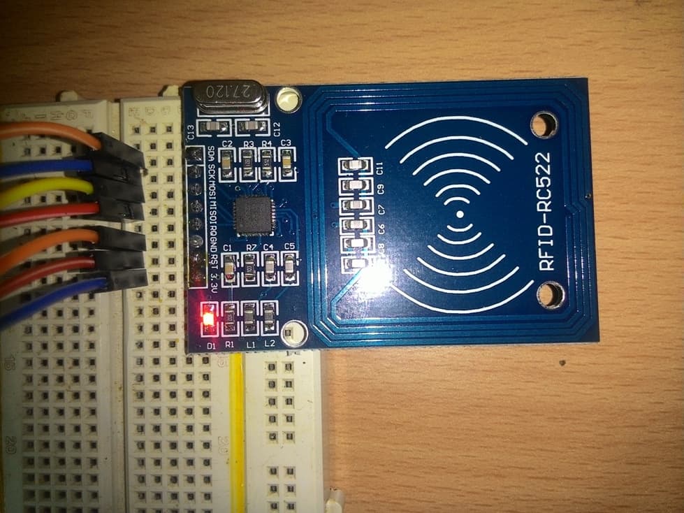
Illustration of RC522 reader/writer module:
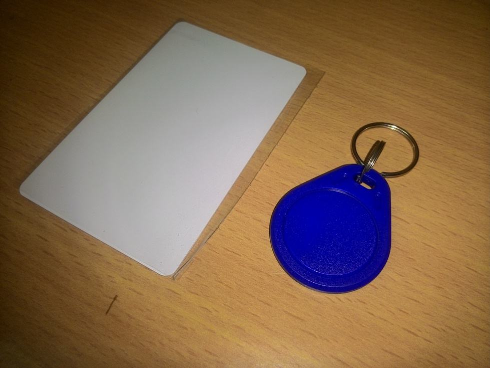
Card and keychain type tags:
As we can see that, a part of the PCB is surrounded by conducting path in square shape on the reader; this will generate electromagnetic field for the tag at 13.56MHz frequency.
The generated EMF is picked by the tag and converts to sufficient voltage for the tag to operate, the tag will sends out the necessary information in pulse form back to the reader. The on-board microcontroller decodes the information.
How it Works
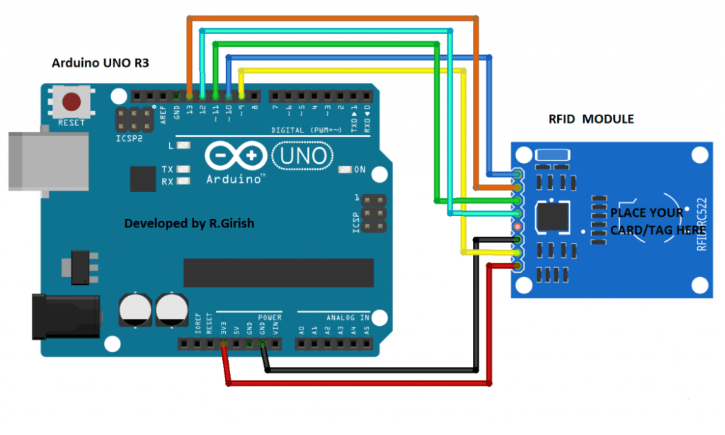
The schematic is very easy and self-explanatory, few jumper wires is enough to accomplish this project. We are going to power the arduino and RFID via USB port of the computer. The operating voltage of RC522 is 3.3V, do not connect 5V supply to the module and will damage the on-board components.
Arduino RFID circuit prototype :
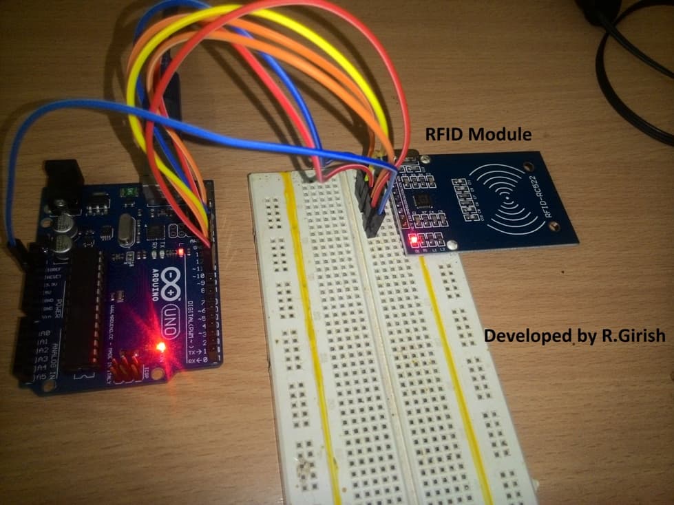
That’s all the hardware connections, now let’s jump into coding.
Before uploading the program, download the library file from the following link and move to library folder of arduino IDE.
github.com/miguelbalboa/rfid.git
Program Code:
//-------------------------Program developed by R.Girish------------------//

#include <SPI.h>

#include <MFRC522.h>

#define SS_PIN 10

#define RST_PIN 9

MFRC522 rfid(SS_PIN, RST_PIN);

MFRC522::MIFARE_Key key;

void setup()

{

Serial.begin(9600);

SPI.begin();

rfid.PCD_Init();

}

void loop() {

if ( ! rfid.PICC_IsNewCardPresent())

return;

if ( ! rfid.PICC_ReadCardSerial())

return;

MFRC522::PICC_Type piccType = rfid.PICC_GetType(rfid.uid.sak);

if(piccType != MFRC522::PICC_TYPE_MIFARE_MINI &&

piccType != MFRC522::PICC_TYPE_MIFARE_1K &&

piccType != MFRC522::PICC_TYPE_MIFARE_4K)

{

Serial.println(F("Your tag is not of type MIFARE Classic, your card/tag can't be read :("));

return;

}

String StrID = "" ;

for (byte i = 0; i <4; i ++)

{

StrID +=

(rfid.uid.uidByte[i]<0x10? "0" : "")+

String(rfid.uid.uidByte[i],HEX)+

(i!=3?":" : "" );

}

StrID.toUpperCase();

Serial.print("Your card's UID:");

Serial.println(StrID);

rfid.PICC_HaltA ();

rfid.PCD_StopCrypto1 ();

}

//-------------------------Program developed by R.Girish------------------//
Ok! What does the above program designed to function?
The above program will display the UID of the tag in serial monitor of IDE, when you scan on the reader. UID is unique identification number of the tag, it can’t be changed and it is set by the manufacturer.
OUTPUT:
Your card's UID: FA:4E:B2 // this is an example.
Note 1: The each two values are separated by colon, which is done by the program; real values may not be separated by colon but, rather by space.
Note 2: Only NXP manufactured RFID tags are readable/writeable with the proposed setup, these are commonly and commercially used.
The UID is used to recognize the tag; the tag that comes along with the kit can store up to 1KB of information. There are other cards which can store up to 4KB of information or even more.
The process of storing and extracting the information from the tag is subject of another article.
If you have question, regarding this project, feel free ask in the comment section.


Questions & Answers
Hello Mr Swagatam. Please I’m now referring my question to Mr GR. Please base on one of your arduino article https://www.homemade-circuits.com/2017/09/password-based-ac-mains-onoff-switch-circuit.html
Please Sir I want to use it as a door lock but using savor motor
Hello Sufiyan, yes you can make it, no problem, but I am not sure how you would implement the reverse forward for a servo motor..
HI oz,
Let me do some research on this, If this is possible for me, I will definitely make an article.
Regards
hi Swagatam
my i’m a locksmith and i use to play with electronics long ago, i fund your website looking for a basic 3 phase motor controller inverter.
your website kept me busy for the past 4 hours so much stuff 🙂 and now i came across this
and sense as a locksmith i make car key’s, i realty need an RFID chip reader.
would if it be possible to modify this one to read and identify car transponder chips? (to display if a chip is still working and what kind it is?)
and maybe even (i know this one has nothing to do with RFID) add an RF signal tester with frequency display (for testing car remotes)
such a tool would help me a lot.
and if i could build one even better, the only thing is.
it has to be a stand alone device (not connected to a computer of any kind (laptop, tablet or cellphone)
no problem to install a raspberrypai with touch screen, or some kind of dot matrix display
Thank you Oz, I appreciate your interest very much, the above article was written by Mr. GR, so I will ask him whether the mentioned idea is possible or not, we’ll get back to you soon.
good evening swaggattam
there was a digital display circuit I want to design, but there is one particular component. I can't found it here in ma country " 2N3053" transistor. Pls can u suggest me another transistor use to replace it. i'll be great and happy if I get responds. thanks
chucks, you can try BD139