In this article I will show how to construct an GSM based LPG leakage SMS alert circuit using Arduino, which alerts the recipient via SMS and surrounding people via beep, when LPG gas leaks out from the LPG cylinder or if there's leakage due to improperly closed valve.
Using MQ-135 as the Sensor
We are going to utilize MQ-135 air quality sensor for detection of rise in LPG gas in air.
If you are not much acquainted with the MQ-135 sensor, please check this article which explains all the basics about the sensor MQ-135:
LPG gas cylinders servers thousands of households every day for food, some may have piped LPG connection from a company or government. We always underestimate the damage caused by gas leakage/explosion, may be because we occasionally/rarely read them on newspaper.
We have to admit that a full or near empty LPG gas cylinder is no less than a dynamite. If we handle them wrongly by intentionally or unintentionally it will end up in catastrophe.
The most of the catastrophe occur due to leakage from the valve of LPG gas cylinder/stove. This is because, users may forget about the food which was cooking and gets into household/other chores. The flame gets off due to liquids surrounded around the burner of cooktop.
The LPG gas keeps coming out of it and finally room get floated with toxic gas, which may explode due to tiny impact, even a static charge.
Similar scenario can be simulated if gas cylinders and cooktops are maintained poorly. The rubber gas tube is the most vulnerable part, where a pinhole gap is enough to escape gas out the cylinder.
The LPG gas itself don’t have any/faint odour, the LPG gas manufacturer add an odour agent, which we could felt by smell. But, everyone have busy life, we won’t be available at site while leakage takes place. So we will place an artificial nose (MQ-135 sensor) inside the kitchen.
When it detects LPG gas and goes beyond pre-set threshold level it beeps and sends SMS to alert the user.
NOTE: The MQ-135 is capable of detecting smoke and other chemical substance in air. The sensor can’t distinguish between them, so if the setup beeps and send SMS alert, you can assume that there is something wrong in kitchen/room.
It could be a burned food or LPG gas leak or even a fire. Simply we can say this is a multipurpose alert system.
The Design:
The LPG leakage SMS alert circuit is fairly simple and its Arduino beginner friendly. The brain is arduino as usual, which analyse sensor readings every second and takes decisions. The GSM modem which used to send SMS alert to recipient phone number. A buzzer is utilized for alerting people around the gas leakage area. You can even replace the buzzer with relay.
Circuit Diagram
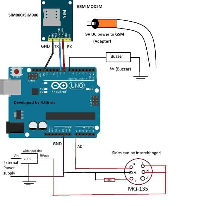
An external power supply is used for heater coil of the sensor. The input for IC7805 must be above 8 volt. The GSM modem must be powered form its DC jack and not hosted from arduino supply.
The ground to ground connection is established between external power, GSM modem and arduino. Use a valid SIM card and make sure that, your SIM has working SMS plan.
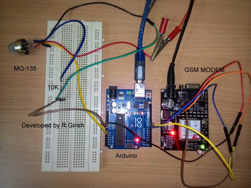
Prototype Image:
Directions for use and Testing:
For testing purpose we need serial monitor, once your calibration is complete, you can power arduino from external power sources.
Don’t use batteries as main supply, it draws few hundred mA from the supply, when the sensor goes below optimum temperature, it gives false alert. However, you can use batteries for backup power with sharp cut-off voltage.
When the user turns the circuit ON, it takes 3 minutes to get optimum temperature for the sensor, until then the circuit is inactive. We can witness from the serial monitor. It displays “Sensor waiting for optimum temperature”.
Once the sensor reaches optimum temperature level, the setup sends a test message to recipient phone number. Once you receive it, you can assume that GSM modem is working fine.
It starts displaying some numbers on the serial monitor, which is voltage level from the sensor. Higher the pollution in air higher the value get printed.
You should study about those values before you set a threshold value. For example: if the you are getting readings between 300 to 350, you should set the threshold in program, twice the value of readings in serial monitor, say 600 for above case (you can set from 0 to 1023), it should not false trigger due to small changes in the room’s air pollution content so, a double or higher value is preferred.
Now bring a cigar lighter near the gas sensor and leak the gas without flaming it. The readings should go high, an SMS alert should be sent and buzzer starts beeping.
Don’t place the sensor directly above cooking area, as the sensor is susceptible to corrosion and reads garbage values due to emission of hot food particles and send false SMS alert.
Program Code:
//--------------Program developed by R.Girish---------------//

#include <SoftwareSerial.h>

SoftwareSerial gsm(9,8);

int input=A0;

int output=7;

int th=600;    //set threshold temperature

unsigned long A = 1000L;

unsigned long B = A * 60;

unsigned long C = B * 3;

unsigned long D = B * 30;

void setup()

{

Serial.begin(9600);

pinMode(output,OUTPUT);

digitalWrite(output,LOW);

Serial.println("Sensor waiting for optimum temperature");

delay(C);

Serial.println("Sending test SMS......");

gsm.begin(9600);

gsm.println("AT+CMGF=1");

delay(1000);

gsm.println("AT+CMGS="+91xxxxxxxxxx"r"); // Replace x with mobile number

delay(1000);

gsm.println("LPG leak, test SMS");// The SMS text you want to send

delay(100);

gsm.println((char)26); // ASCII code of CTRL+Z

delay(1000);

Serial.println("Test SMS sent.");

}

void loop()

{

Serial.println(analogRead(input));

delay(1000);

if(analogRead(input)>th)

{

delay(5000);

if(analogRead(input)>th)

{

Serial.println("Sending SMS............");

Serial.println(analogRead(input));

gsm.println("AT+CMGF=1");

delay(1000);

gsm.println("AT+CMGS="+91xxxxxxxxxxx"r"); // Replace x with mobile number

delay(1000);

gsm.println("Warning: LPG gas leak detected");// The SMS text you want to send

delay(100);

gsm.println((char)26); // ASCII code of CTRL+Z

delay(1000);

Serial.println("SMS sent.");

digitalWrite(output,HIGH);

delay(B);

delay(B);

digitalWrite(output,LOW);

delay(D);

}

}

}

//--------------Program developed by R.Girish---------------//
Note: Replace th=600 with your own value.
int th=600; //set threshold temperature
Replace x with recipient phone number. You need to place the recipient phone number at two places in the program.
gsm.println("AT+CMGS="+91xxxxxxxxxx"r"); // Replace x with mobile number
Dear Swag,
May I have the simple diagram on connecting Sim900A to the Arduino Uno?
Sorry Willy, I have not studied it yet, so don’t have any idea regarding this.
Sorry sir could you explain arduino and how it works and do you have a circuit to make one.
Really appreciate your feedback
Glad you liked them Noel, however the Arduino articles were written by another author, my expertise is in the filed of discrete electronics not Arduino, so I won’t be able to help you in this regard.