In this article I will show how to construct an interesting project, which could potentially enhance your brain’s capability. I have explained how to make a TDCS brain stimulator circuit.
Overview
This may sound like science fiction, where an evil scientist connects his head to some complex machine and gaining super human capabilities.
This may somewhat be true, but not as sensational as in sci-fi.
Here I have explained what TDCS is, how it improves brain activity and how to make one.
WARNING: Proceed this project at your own risk. We are not responsible for any damage or loss caused by this project.
Brain is one of the complex organs in our body without which it’s impossible to stay alive. A supercomputer takes millions of joules of energy and thousands of CPU cores and takes several minutes to simulate equivalent to one second of brain activity, whereas our brain might just need a burger for powering itself for few hours, it is estimated that brain consumes equivalent to power of a 20 watthour light bulb.
Our brain is a pool of electrical activity; we can measure brain’s electrical activity by means of bio-medical instruments such as EEG. Any abnormality in brain leads to change in electrical activity of brain.
We can fix quite a few diseases such as depression, chronic pain etc by applying small current at specific point of our head, which can potentially cure or suppress the disease significantly.
This method is used where drugs don’t respond to treatments or drugs are too expensive.
NOTE: Never confuse TDCS with “Electroconvulsive therapy” which is popularly known “shock treatment”.
What is TDCS?
TDCS is a medical tool. TDCS stands for “Transcranial direct current stimulation” which means passing direct current (DC) through skull for stimulating the brain.
This is a non-invasive method and this technique is practiced by many doctors across the globe and has been recommended safe.
This method gained more attention of many researchers in recent years and they found encouraging results from their experiments.
Researchers found improvements in math ability after passing small current for few minutes through the brain of the participants; this is one of many positive results.
This method is used by US air force and army for improving their skill and speed up decision making reflexes.
Basically, the TDCS device is powered by only batteries and consists of current controlling mechanism which control current through the brain.
TDCS many have two or more electrodes, but basic one consist of at least two electrodes, one is positive and another negative.
The electrode is made of soft material and soaked with electrically conductive solution such as sodium solution, for homemade projects we can use table salt mixed in water.
The soft material prevents skin irrigation and provides good conduction between the electrode and skin.
The electrode placement around the head and size of electrode plays an important role in controlling neural activity.
Improper placement of electrodes may not give optimum results and also may leads to negative impact on our brain.
Here is an image illustrates sample electrode placement:
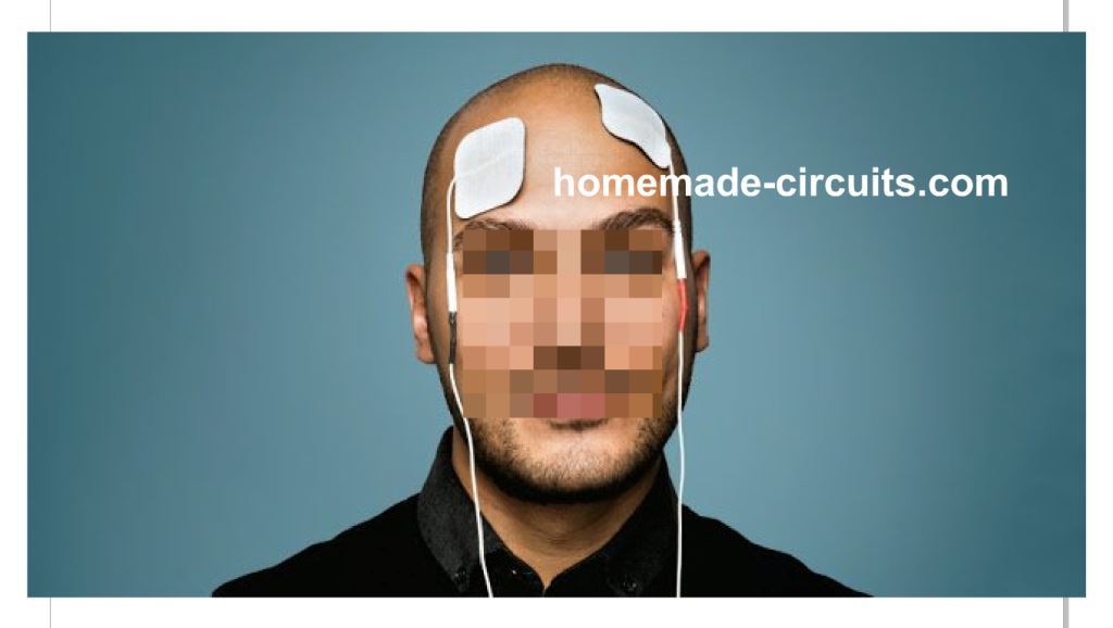
Warning: You are advised to do extensive research on internet regarding the placement of electrode and the size of electrode.
Any side effects?
TDCS method is not new in medical field, but relatively less study has been conducted till date. But most of the study have revealed positive results. Here are a few side effects:
• Skin itching around the electrode placement.
• Head ache for few participants has been observed.
• Hallucination for few minutes observed in few participants.
The long term affects are yet to known.
Positive effects:
• Improved math skills.
• Improved decision making skills
• Improved gaming skills
• Potential tool for curing many diseases such as depression, Parkinson, stroke, chronic pain etc.
• Improved sleep quality.
NOTE: The above skills could be enhanced by placing the electrode at different position on head. Improper placement of electrode leads to negative impact on our brain. So, do research on internet about placement of electrode on head.
The Design:
So, now you know quite a bit about TDCS. Now let’s construct the TDCS device.
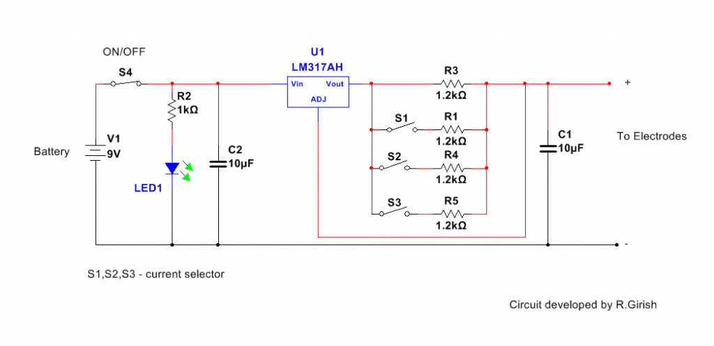
The TDCS consist of constant current source for proper current regulation, it must be operated only on batteries, please forget about AC mains here.
There are three current switches for regulating output current. Different treatment needs different current flow through head.
All OFF - output 1mA.
S1 ON - output 2mA.
S1 and S2 ON - output 3mA.
S1, S2 and S3 ON – 4mA.
Circuit Diagram
Here’s how to make an electrode:
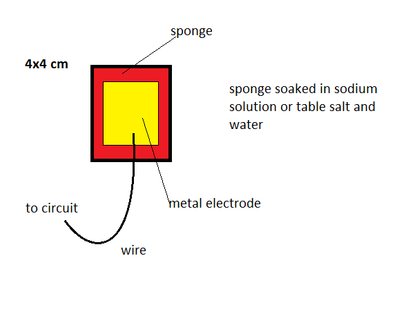
The sponge must place on the skin not the metal part. Please don’t use any kind of metal electrode to contact with skin; it will cause small skin burn even at 1mA. Do not use AC mains for power supply, small surge is enough to flow huge current on your head.
Conclusion:
TDCS is a medical tool has potential capability to cure many diseases, if you have proper knowledge about it you can use without consulting a doctor but, be always cautioned, don’t take our word for that. Do research about it before getting into use.
I have been looking at this circuit for a long time I guess and since, I am not a electronics student it took me much time to learn. I am hoping that your are still active to reply to my post. My question is : Since a LM317 requires 2 resistances (one between adj and Vout and another between adj and ground) should there be a connection between adj and the negative battery terminal?
Can I write to you for more collaboration?
Hi, the LM317 in the above circuit is not wired as a voltage regulator, rather it is wired as a current regulator.
The ADJ pin will need to be connected to ground through a resistor in a voltage regulator circuit, not in current regulator.
Please let me know if you have further doubts regarding the subject….
Thank you for your response. Glad to see that you still take an interest in such an old thread. I was looking at some commercially available TDCS device and one of them mentioned that the maximum voltage reached is up to 80v….which is obviously not possible in the LM317. Any suggestions on what current regulator may have been used?
You are most welcome!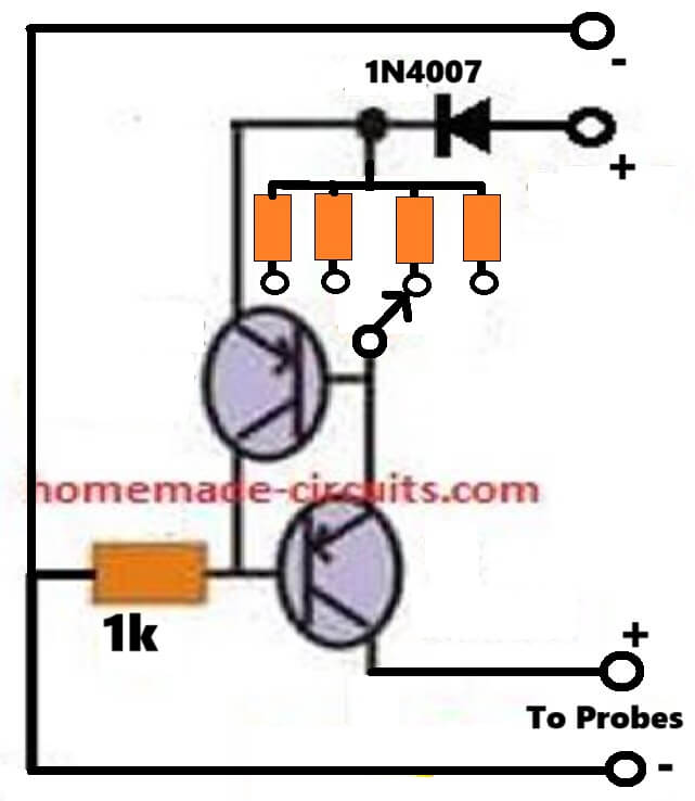
For 80V inputs you can try the following transistorized version of the circuit. The BJTs can be any 100V 100mA PNP BJTs.
The current limiting resistor values can be calculated using the following formula:
R = 0.7/Output Current
" rel="ugc">
I tried modifying the circuit so that I can get a range of current. Also, the usual impedance of the human head is in the range of 1000-1500 ohms. This modification allows for voltages which can deliver 4mA currents at that resistance. It also, has the disadvantage that it can exceed 16mA which is when the bad effects kick in. I wanted to hear your opinion on the circuit and if I am making any mistakes. Additionally, it will helpful if you can suggest how to get the output? Should I use audio jacks?
Your circuit is correct, but you wanted an 80V input circuit, right? so LM317 will not handle it.
Thank you for answering that too on a Sunday. I am starting out with this 36v version and I will eventually try to build the 80v version. But that brings me to another aspect. Impedance measurement is an important part of TDCS. If the impedance is too high, the effect becomes less even if the current is constant. Can you please suggest an impedance measuring circuit?
Thank you for your feedback. I don’t have an impedance meter circuit with me right now. Instead of an impedance meter, you can add a milliammeter in series with the output of the Lm317 circuit and then adjust the current according to the readding on the meter.
Do we have to soak the sponges in sodium solution every time we use the device, or do we just have to do it for the first time only. Also are the sponges re-usable, or should we use new sponges every time we use the device/
According to me you will have to soak the sponge every time you use it. Sponges are generally reusable.
Hy sir, is there any place or website in India from where we can buy tdcs device? Or if you are selling tdcs do let me know the price please.
Hi Chirag, Sorry we don’t sell TDCS and I have no idea from where it can be purchased
As the battery starts draining out, will the intensity of the current also reduces?
Yes, as the battery drains, the current will also reduce.
Hy Sir, can you please name all the items that are displayed in the circuit which are required to make tdcs.
Hi Chirag, all the numbers are clearly mentioned in the diagram, please let me know which part number you are not able to understand?
All the resistors are 1/4 watt 5%
Capacitors are 10uF/25V electroltic.
Yeah got it, thank you. Also lets say if I want to withdraw a current of 5mA from the circuit, I just have to add a switch and 1.2k-ohm resistor right? Also is this device available anywhere in india to buy?
Yes that’s correct.
Also, you can use a single fixed resistor instead of switching all the 4. You can use the following formula for calculating the resistor
R = 1.25 / output current
R = 1.25 / 0.005
= 250 ohms
Hi Sir . Swagatam,
first, im very glad that i fund your very interesting siteweb and rich informations for especially for biggener amator…i seen your nice project about tDCS stimulator and really will be very happy you not imagine that if you help me and finifh your nice generous job by making a tACS STIMULATION FROM 0 TO 2 mA of output with real AC Current and Frequency with optimal contact quality with skin..
i like have a normal circuit schema diagram and PCB .
Amically,
karim
Thank you Karim, and glad the site information is helping you!
Please see the following diagram,You can try this. However the output will be a square wave AC.
Hi sir,
Just browsing your site and I came across this comment, this circuit suggestion looks really dangerous for medical purpose, it should be isolated from mains using a transformer at least. But still the circuit arrangement should run on a battery using IC555 multivibrator (say) and H-bridge for TACS application.
Regards
Girish
Thank you Girish, for notifying the issue! I appreciate your comment.
Technically if you see the output has negligible current since it is protected with 6nos of 56K resistors and a capacitor, but you are right since it is a human body is involved we cannot afford to take any risks.
I will soon replace the diagram with a 555 AC generator circuit.
I both a lifelong musician and an electronics designer. I also suffer from a case of Essential Tremors, which is considered mild, but is very annoying to a guitarist trying to play his instrument while the left hand fingers tremor and work against the obvious need for control. I’m also a DIY experimenter, and as such have found some exercises and supplements that help. Now I want to experiment with TDSC. Its lucrative to try because a procedure called DBS is known to be very helpful, but it requires surgical implanting of electrodes in the brain. But I have a problem trying this, as a typical “hippie” musician with considerable hair. It doe not seem like it will be practical for me to try this unless I can work with much smaller electrodes, perhaps held in place with a headband. Something that won’t require shaving my head to try. Unfortunately the resistance I measure pressing two blunt/rounded pieces of metal against either side of my head is around 10 megaohms. Ohms law tells me I’d need about 20000 VDC. Obviously impractical. I don’t suppose anyone could recommend a workaround?
I wish I could help, however, I cannot suggest much on this since it is strictly a medical related subject and will require qualified testing and verification from an authorized source.
By the way, our skin’s response to electricity cannot be analyzed through Ohm’s law, even a tiny electrical stimulation is enough for our body to react and respond appropriately to it.
I understand no medical advice would be appropriate. But I also realize that no suggestion could help change the laws of physics for me. If most of the articles on this subject mention an approximate 2 mA target current, it makes sense that the smaller the contact area the less chance of reaching that current with a safe voltage. Thanks though. I will at least try adding some small sponges soaked in salt water added to my electrodes, or maybe at least add more small electrodes to the headband I prepared.
OK thanks!
This is not the proper circuit, rather look for Bob Becks brain tuner.
hi could you pls make list for requirement items
All the resistors are 1/4 watt 5%, capacitors are 10uF/25V
Ciao, sì, puoi utilizzare qualsiasi versione di LM317 IC nel circuito descritto sopra