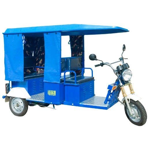
In this post I have explained a simple solar electric rickshaw or E rickshaw circuit which can easily built by anybody at home and used with a locally fabricated vehicle. The idea was requested by Mr. Amit.
The Design
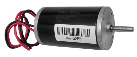
Selecting a BLDC
In one of my earlier posts I presented an idea which could be effectively used for making an electric scooter using a BLDC motor and associated circuitry.
In this post I have explained a similar concept but without using BLDC motor just for the sake of simplicity.
Although using an ordinary brushed motor could appear to be inefficient compared to its BLDC counterpart, a brushed motor nevertheless eliminates the need of complex BLDC driver circuitry and the involved complicated wiring with the motor making the design extremely simple and layman friendly.
Moreover, a brushed motor can be operated by using an ordinary IC 555 PWM circuit, quite unlike a BLDC motor which requires much sophisticated control ICs which are not only difficult to find in the market, but are always vulnerable of becoming obsolete, risking the guarantee period of a E-rickshaw which might have incorporated that particular chip.
PWM Controller
A simple PWM circuit using IC 555 can be used for controlling the speed of the E-rickshaw by controlling the speed of its attached control motor.
The PWM concept makes sure that the energy consumption of the motor is significantly reduced and the efficiency is increased to the maximum possible range.
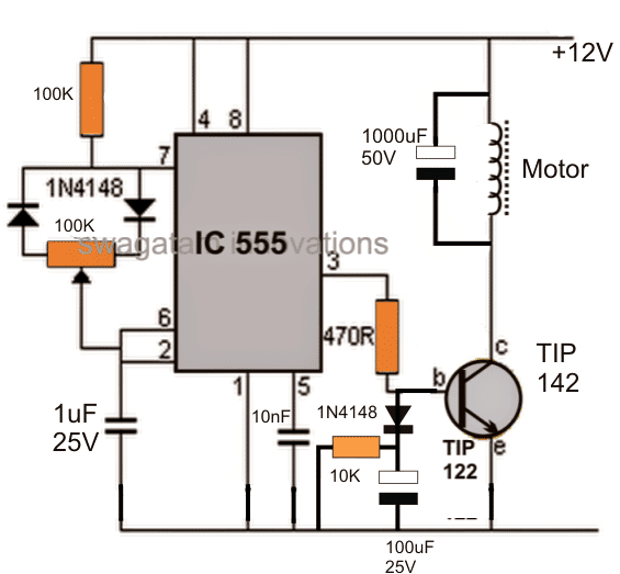
The 100k pot associated with the two 1N4148 diodes becomes responsible for varying the output PWMs at pin#3 of the IC, which in turn determines the conduction rate of the TIP142 transistor and the speed of the connected motor. For higher current, the TIP142 could be replaced with equivalently rated mosfet.
The 100uF capacitor at the base of the transistor makes sure that whenever the E-rickshaw is initiated, it delivers a slow soft start to the motor, rather than with a jerk or at a higher initial torque.
The potentiometer should be of very high quality so that it is able to sustain the frequent speed control operations and may last for many many years without going through fatigue or mechanical wear and tear.
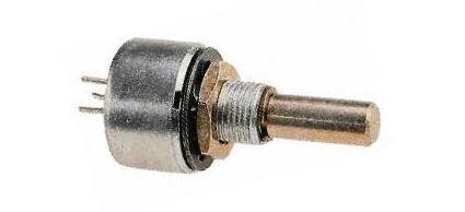
Typical specifications of the pot should be as given under:
Made up of Cermet or carbon moulded element.
Approved by BS and CECC
Rated at 2 watt at 70 degrees C, in Cermet
Rugged construction
Military standard layout
Container sealed with MC1/MH1 standards
Stiff, silver plated terminals.

How the Speed Control is Installed
The speed control pot knob could be favorably installed in the handle of the E rickshaw, near the thumb of the driver, so that controlling the speed of the rickshaw could be executed with maximum ease, and minimum effort.
The ON/OFF switch of the circuit should be also accessible near the thumb of the driver installed on the handle, so that the driver is able to switch OFF the system immediately during a critical or a catastrophic circumstance.
The Brakes
Th braking mechanism of the proposed electric rickshaw could be built using the conventional technique, however it must include a push-switch which may be in series with the supply voltage to the motor circuit, and must be configured in such a way that when brakes are applied the switch is first deactivated, switching OFF power to the IC 555 circuit and the motor.
This makes sure that before the braking system hits the wheel axle, the motor is disabled first preventing its interference in the braking procedure.
Solar Panel Integration
In order to convert the proposed E rickshaw into a power saving solar electric rickshaw, a solar panel may be integrated with the system, as I have explained below:
Although primarily the battery of the vehicle will need to be charged from an AC mains operated charger quite often, the solar panel will act like a secondary back up charger, and help reduce electric consumption of the vehicle which in turn will help to save power and money for the end user.
Preferably the solar panel could be mounted on the roof of the vehicle and therefore could be as big as the size of the roof top of the E rickshaw, and rated at around 30V, 5 amps which looks quite economical for the proposed system.
With the above specified solar panel, no additional charger controller would be required as the voltage from the panel would automatically self adjust with the 24V battery specs, making the unit even more cost effective.
The solar integration ensures that the vehicle battery is kept on a topped-up condition whenever the vehicle is idling and thus help to increase the efficiency of the vehicle substantially.
The Battery
For a reasonable three seater E rickshaw including the driver, a 24V 20 amp motor would be just enough (assumed value), and to operate this motor optimally throughout the day, a 24V 200AH battery would do just well, although the user could alter the AH specs according to the needs and suitability of the vehicle's operational schedule.


Questions & Answers
Hi
I am trying to get hold of a diagram and parts list of the speed controller that is sold on Amazon / eBay it is a brushed dc 10 to 55v reversible type, the reason for asking is I am trying to repair one that I overloaded.
Regards
Steve
Hi, you can try one of the designs presented in the following post:
2 Simple Bidirectional Motor Controller Circuits Explored
Olá como vai? Fiz o circuito pwm com ci 555, mas a variação de velocidade quase não é percebida, o que pode ser? Obrigado.
Olá, Se você está tendo um osciloscópio, verifique a forma de onda nos pinos3 do IC e no terra e verifique se os PWMs estão variando ou não quando você gira o potenciômetro. Isso confirmará a situação
Thanks for the work you are doing here sir.
I have tried this and it worked well for my small electric scooter as I replaced the tip122 with irf3205.
I have a challenge mounting this circuit on my scooter because my scooter has a hall sensor twist throttle and not a potentiometer as in the circuit.
Please how do I replace the 100k potentiometer with the hall twist throttle?
Thanks
Thanks Ako,
you can use the following circuit:
remember the throttle module will require a 5V DC which you can acquire from the main battery bank via a 7805 regulator or through any other step down method.
The throttle output must be connected to the indicated input at pin#5 of IC2
Hello dear swagam.
I appreciate that fact that you share you experience with the world, may you live long to keep helping.
I have tried this circuit using the irf3205 mosfets and it works well for a small 12v 1A motor but when a try it on my scooter whose motor is rated 24v 28A it starts but would not stop unless I disconnect the power source. I even double up the Mosfet and the result where as the Mosfet is rated 55v 120A.
Please I need your help
Hello Ako,
yes you will have to disconnect the power to stop the motor for ensuring a guaranteed halting of the vehicle. I hope I have understood your question correctly.
reverse?
I am glad you're enjoying my site and it's helping you to learn some electronics 🙂 as far as learning and exploring new things is concerned age can be never be a barrier…so do feel free to ask, and question whatever you will intriguing, I'll try my best to help you out.
thanks for your timely answers and your time. i read this post a couple of times and it dawned on me after the "laymens" term employed was one of the reasons i enjoy your site(s) so much. I do realize this is a sight from the mid-eastern part of the world after reading the posts comments and some of the components which are deemed archaic here in the u.s.
but the laymens terminology is one of my favorite words as an instructor for the machine rebuilding classes i taught to tradesmen. i am a class 1a machinist just have a nack a level above the rest. Computerized machinery fell in my lap where i worked at around the same time i had purchased my first "radio shack coco" computer. the machines were not that "brainy" at the time but i was ahead of the rest , even the companies' engineers.
now after retirement i tinker with electronics and scounge/dumpster diving for discarded electronics and stocking my components cabinet.
the machines had to be diagnosed(my job) and the controls were plug and play modules very similar to todays ardueenio's. I despise them as i never learned the art of electronics and building these circuits.i mean i have built some circuits using forest mims books from the 80's then talking electronics and now a dozen or more forums and sites as yours.
so herei is a new student of 16 getting near 61. this is for you and not really meant to publish.
a DPDT relay will be required with a separate switch for initiating the reverse movement of the motor
which type of cap for the 1uf 25v? i think the 10nf is ceramic cap and "what" wattage should the resistors be. i am currently operating a three wheel jazzy type 3 wheel scooter with a trailer i converted to a 12v starter motor to help with my yard work. i have been using a 12v 40 amp automotive relay. works fine but will do a wheelie now and then! yeah it's a little touchy!
the motor should be preferably brushed, DC type for the explained 555 PWM circuit
1uF/25V can be an electrolytic
moter RPM and v talk me