• Skip to main content
  • Skip to primary sidebar

Homemade Circuit Projects

Need circuit help? Post them in the comments! I've answered over 50,000!

Blog | Categories | About | Contact | Calculators-online
You are here: Home / Automobile Electronics / Make this Car Interior Light Fader Circuit

Make this Car Interior Light Fader Circuit

Last Updated on January 1, 2019 by Swagatam 9 Comments

In this post I have explained a simple circuit which can be used for producing a slow fading light effect each time it's switched OFF. The application can be typically used in car interior lights.

Table of Contents
  • The Circuit Concept
  • How it Works

Designed by: Abu-Hafss 

The Circuit Concept

Most of the modern cars are equipped with circuitry which switches on the Car's room lamp when a door is opened and switches off the lamp in fading manner when the door is closed.

Here a simple circuit is presented which can be installed in old cars without any major alterations to get the same effect.

Before we understand the description of the circuit, it is important to understand the wiring of a Car's interior lamp and how the door switches are operated.

warning message: electricity is dangerous, proceed with caution
carinteriorlamp 1

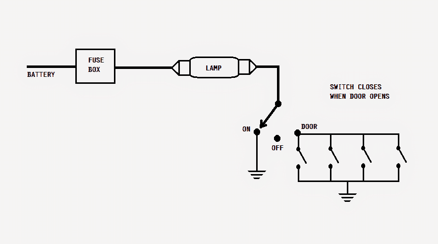
The lamp is connected to the battery's positive thru a fuse. The other end of the lamp is connected to a single-pole-3-throw switch.

When this switch is positioned at ON, the other end of the lamp gets connected to ground i.e. the negative terminal of the battery hence, the lamp gets illuminated.

In OFF position, the lamp remains disconnected from the ground. In DOOR position, the lamp gets connected to the ground via door switches (in parallel). When a door is opened, the corresponding door switch is closed.

carlightfader 1

How it Works

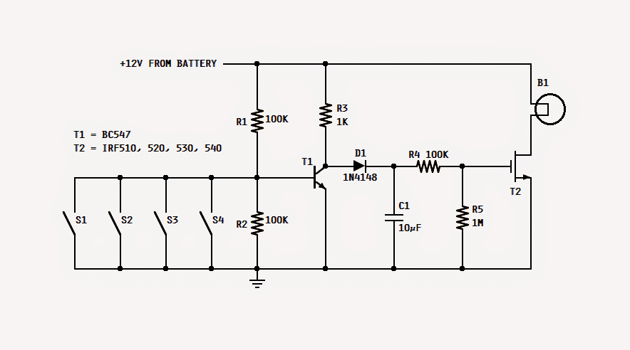
Referring to the proposed car interior light fader circuit, when any of the door is opened, its switch is closed hence, the base of T1 gets connected to ground and thus stop conducting. In this state, C1 gets charged rapidly via R3 and D1.

As soon as C1 is charged, the mosfet is fed with the gate voltage thru R4 and thus it starts conducting and consequently the lamp is illuminated.

Now, when that door is closed, its switch gets open. The base of T1 gets disconnected from the ground and is held at a voltage delivered by the R1/R2 voltage divider.

This action switches on T1, and the voltage coming from R3 finds it way to ground thru emitter of T1.

The switching on of T1 deprives C1 of its charging current and thus C1 starts discharging slowly thru R4 and R5. The gate voltage of T2 reduces as C1 discharges.

With this reduction in the gate voltage the intensity of the lamp is also reduced. Finally, when the gate voltage goes below the threshold voltage the lamp switches off.

The values of R5 and C1 are responsible for the fading delay time of the lamp. Increasing the values will increase the time and vice versa.

T2 should be any suitable N-channel mosfet capable of handling at least 50V and 10A. The whole circuit can be built on compact sized general purpose board and enclosed in the room lamp cover.

You'll also like:

  • 1.  Understanding Motorcycle Voltage Regulator Wiring
  • 2.  Simple Capacitive Discharge Ignition (CDI) Circuit
  • 3.  Speed Dependent Brake Light Circuit
  • 4.  Build a Homemade GSM Car Security System
  • 5.  Simple Electronic Fuse Circuit
  • 6.  Automotive Trailer Lights Interface Circuit

About Swagatam

I am an electronics engineer with over 15 years of hands-on experience. I am passionate about inventing, designing electronic circuits and PCBs, and helping hobbyists bring their projects to life. That is why I founded homemade-circuits.com, a website where I share innovative circuit ideas and tutorials. Have a circuit related question? Leave a comment.... I guarantee a reply!

Previous Post: « Simple Cellphone Jammer Circuit
Next Post: SG 3525 Automatic PWM Voltage Regulation Circuit »

Reader Interactions

Comments

  1. George says

    November 11, 2022 at 8:50 pm

    Hallo!

    I am a civil engineer, and i don’t know much about electronics. But i have 1 question. Won’t that circuit eventually drain the battery of my car (if i leave my car parked for a period of time), through the R1 and R2?

    With regards.

    Reply
    • Swagatam says

      November 12, 2022 at 10:23 am

      Hello, yes that can happen. However the lamp power can be very small which might allow a very long time for the battery to drain. Alternatively you can use LED lamps to make the draining process negligible.

      Reply
  2. Patrick says

    August 17, 2020 at 7:51 pm

    Hi Swagatam,
    Just one more question if you don’t mind? What transistor do you recommend for my application?
    Thanks again for all your help so far
    Regards
    Patrick

    Reply
  3. Patrick says

    August 16, 2020 at 12:32 am

    Will this circuit also work with an led light. ie for the ignition switch so you can see where to put the key at night. I am thinking just one LED. Thank you for your kind assistance. Regards, Patrick

    Reply
    • Swagatam says

      August 16, 2020 at 9:10 am

      Yes sure, just replace the lamp with an LED having a series 1 K resistor.

      Reply
      • Patrick says

        August 17, 2020 at 6:19 pm

        Thank you very much Swagatam. I appreciate your help and advice. I will try this circut and see how to make the timing 10 seconds by playing with the capacitor and resistor combination. I have som small N channel mosfets which I will try. I doubt that I need a 10 amp mosfet for a single LED.
        Thanks again.

        Reply
        • Swagatam says

          August 18, 2020 at 9:38 am

          Thanks Patrick, yes for an LED a 10 amp transistor will not be required, you can use a BC547 instead.

          Reply
          • Patrick says

            August 18, 2020 at 1:15 pm

            Swagatam,
            Thank you for the answers to my questions. As you will no doubt have gathered that I am not very knowledgeable with electronics so I find it very helpful that you and people like yourself go to the trouble of helping people like myself and I am very grateful. I have lots of BC547’s in my box so I will breadboard the circuit today and let you know how I get on.
            Regards
            Patrick

            Reply
            • Swagatam says

              August 18, 2020 at 5:33 pm

              No problem Patrick, please go ahead!

              Reply

Need Help? Please Leave a Comment! We value your input—Kindly keep it relevant to the above topic! Cancel reply

Your email address will not be published. Required fields are marked *

Primary Sidebar

Subscribe to New Circuit Ideas

Categories

  • Arduino Projects (87)
  • Audio and Amplifier Projects (132)
  • Automation Projects (17)
  • Automobile Electronics (101)
  • Battery Charger Circuits (83)
  • Datasheets and Components (104)
  • Electronics Theory (143)
  • Free Energy (37)
  • Games and Sports Projects (11)
  • Grid and 3-Phase (19)
  • Health related Projects (25)
  • Home Electrical Circuits (12)
  • Indicator Circuits (14)
  • Inverter Circuits (87)
  • Lamps and Lights (142)
  • Meters and Testers (69)
  • Mini Projects (46)
  • Motor Controller (64)
  • Oscillator Circuits (27)
  • Pets and Pests (15)
  • Power Supply Circuits (108)
  • Remote Control Circuits (50)
  • Security and Alarm (64)
  • Sensors and Detectors (101)
  • Solar Controller Circuits (59)
  • Temperature Controllers (42)
  • Timer and Delay Relay (49)
  • Transmitter Circuits (29)
  • Voltage Control and Protection (37)
  • Water Controller (36)

Calculators

  • Battery Back up Time Calculator
  • Capacitance Reactance Calculator
  • IC 555 Astable Calculator
  • IC 555 Monostable Calculator
  • Inductance Calculator
  • LC Resonance Calculator
  • LM317, LM338, LM396 Calculator
  • Ohm’s Law Calculator
  • Phase Angle Phase Shift Calculator
  • Power Factor (PF) Calculator
  • Reactance Calculator
  • Transistor Astable Calculator
  • Transistor base Resistor Calculator
  • Voltage Divider Calculator
  • Wire Current Calculator
  • Zener Diode Calculator
  • Filter Capacitor Calculator
  • Buck Converter Calculator
  • Boost Converter Calculator
  • Solar Panel, Inverter, Battery Calculator
  • Wire Current Calculator
  • SMPS Transformer Calculator
  • IC SG3525, SG3524 Calculator
  • Inverter LC Filter Calculator

People Also Search

555 Circuits | 741 Circuits | LM324 Circuits | LM338 Circuits | 4017 Circuits | Ultrasonic Projects | SMPS Projects | Christmas Projects | MOSFETs | Radio Circuits | Laser Circuits | PIR Projects |

Recent Comments

  • Swagatam on How Shunt Regulator TL431 Works, Datasheet, Application
  • SA on How Shunt Regulator TL431 Works, Datasheet, Application
  • Swagatam on Timer Based Cell Phone Charger Circuit
  • Nitesh Agrawal on Timer Based Cell Phone Charger Circuit
  • Swagatam on Timer Based Cell Phone Charger Circuit

Company

  • Privacy Policy
  • Cookie Policy
  • About Me
  • Contact
  • Disclaimer
  • Copyright
  • Videos
  • Sitemap

Social Profiles

  • Twitter
  • YouTube
  • Instagram
  • Pinterest
  • My Facebook-Page
  • Quora
  • Stack Exchange
  • Linkedin
  • © 2025 · Swagatam Innovations