This article describes a simple circuit which can be used for pulsing an electromagnet. The IC 555 once again becomes the central part of the circuit. I have explained the making procedure of this simple adjustable electromagnet circuit for varying the magnetic power of an electromagnet.
Introduction
The circuit was requested by Mr.Jason, one of the followers of this blog. Though I'm not sure of the application needs, the circuit probably can be used for controlling the average magnetic power of an electromagnet or rather the circuit may be considered an adjustable electromagnet circuit.
The circuit involved is quite basic and has been already employed in many applications, explained in my earlier posts. Here the application is quite similar to the earlier ones, that is controlling the output load through a series of varying pulses or through PWM method.
Circuit Operation
The mark/space ratio can be appropriately adjusted using the shown configuration, which in turn can be used for varying the response of the output load.
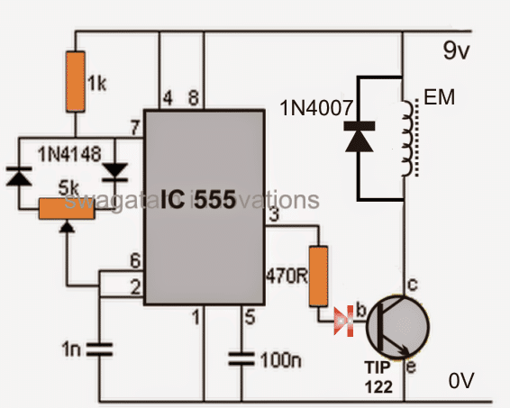
Here the output load is an ordinary homemade electromagnet, connected via a power transistor TIP 122.
The power of the electromagnet is at the maximum level when the pot is set for achieving high mark levels than the space levels and vice versa for reducing the magnetic effects of the electromagnet.
The electromagnet may be procured ready made or can be hand made at home using suitable lengths of enameled copper wire wound over a magnetic core, like an iron nail or rod etc.
The diode connected across the electromagnet protects the transistor from back emf fluxes of the electromagnet.
The circuit may be powered with voltages between 5 and 12, but the current must be appropriately rated, otherwise the circuit will fail to operate.... if a battery is used, make sure it's rated at least at around 1 Ah.
Once powered, this adjustable electromagnet circuit will enable smooth adjustments of the attached electromagnet's magnetic field from zero to maximum.
Circuit Diagram

Questions & Answers
Firstly,What is the wattage of 470 resistor? And secondly what would happen if frequency goes beyond 500 hertz?
What type of diode connected to the base of transistor?
It is a red LED…
All resistors are 1/4 watt 5% rated, higher frequencies will cause the EM to heat up….
Please how can I store a low frequency AC field into battery
That is not possible. Only DC can be stored in a battery.
I believe there are enough circuit examples out there to cover most situations if all one wants is a circuit that will work for their application with minor modifications maybe but a detailed explanation of how exactly these circuits work would be your most valued contribution to your followers.
It is basically a variable PWM generator, meaning the ON/OFF timing of the pin3 output can be independently varied with the help of the pot. The ON time pulse can eb narrower or wider and vice versa with the pot which in turn decides the ON time of the transistor and the EM.Higher on time causes the EM to be more powerful, and lower ON time causes it to be weaker proportionately.
To know how the IC generates the PWM you can read the following article:
How to Generate PWM Using IC 555 (2 Methods Explored)
I ran across this while designing a similar circuit.
Do I understand right that this will continue to pulse on/off as long as it is connected to the power source? The 555 is in astable mode in your circuit?
My circuit simply needs to pulse once when triggered. So I am trying to use the 555 in monostable mode. Currently my Pin2(Trigger) does not connect to Pin6(Threshold), but rather Pin2 is held high and has a momentary switch to ground.
I am not using Pin4(Reset) at all. Should I be using Pin4?
yes pin4 must be connected to the positive, otherwise the monostable will not work, you can refer to the following article for more info
https://www.homemade-circuits.com/interesting-timer-circuits-using-ic-555-explored/
Thank you so much for the help first of all!
Here is the circuit I have made:
https://drive.google.com/file/d/1HpHsFmg-9jpJaUBxJk0j6bNp1zXPClxJ/view
Your linked article says
“As per one of the characteristics the IC, once triggered it stops responding to any subsequent triggers, until the timing cycle is completed. But if one wants to terminate the timing cycle, this can be done at any moment by applying a negative pulse or 0 V to the rest pin 4.”
For my application, I very specifically don’t want it to be possible for the timing cycle to be terminated.
The circuit is working fine at the moment. I know connecting Pin 4 to the positive prevents unwanted resetting. What might cause that unwanted resetting? Is that the only danger of not connecting Pin 4?
Glad your circuit is working, as far as I know pin4 of IC 555 must be compulsorily connected to the positive line, otherwise the circuit might fail to work correctly, you can try it practically and check how it responds
swagatam sir…. i have a 3 cable setop boxes… one has got a signal dropping problem which autimatically shows no signal after two or tgree minutes i have to switch on n off the supply of it then it worrks again n vice versa… another one shows on indicator but diesnt gives video out put at oll.. or like it doesnt takes the signal out put. .
Aqib Noor
Electronic n Electrical Technician…
I am sorry Aqib, i have no idea regarding signal processor units because these normally work with extremely sophisticated and complex circuits..
Making a micro controller based project and my project is a crane that will also have an electromagnet for picking up objects, would this circuit work for that?
the 555 section might not be required for your application, just feed the MCU output to the transistor base for controlling the EM.
Could an LED display be added to this to visibly display the intensity of the magnetic field as it changes?
you can add an LED in series with the transistor base, this will enable the required indications…
you can use an iron bolt and wind some 200 turns of 0.5mm magnet wire….but with an iron as the core make sure to reduce and fix the frequency of the IC 555 anywhere between 50 and 500 Hz not above this
What do you make the EM out of that would work best, wrap the red copper on an Iron Nail or sometype of Ferrite piece and if so, exactly what would i look for to purchased for it, thanks.
Hi! I was about to make something like this, since i need to test the speed sensor of my motorcycle (or modify the mileage, since i've buyed a new gauge that start from 0KM) but in a fast way (using high hz/Khz in the output of 555). So pulsed needed to simulate the wheel spining. This will work right? Thanks!
Yes, it will work in that way as it would effectively simulate the pulses acquired from a rotating wheel.