The discussed Earth leakage circuit breaker diagrams will monitor the leakage current level of the earthing line of your house electrical sockets and will trip the appliances as soon a fault is detected. Here I have explained 2 designs, first using transistors only and the second using IC LM324.
Introduction
If anything goes wrong with them it will instantly switch off the mains and stop any further associated loss. A simple ELCB circuit is discussed here.
A simple circuit of an Earth leakage circuit breaker also called ground fault circuit interrupter is discussed in this article.
The circuit once built and installed will silently monitor the “health” of the earth connection of your house and the connected appliance.
The circuit will immediately switch off the mains on detecting a missing earth connection or a current leakage through the appliance body.
Why You Need an ELCB
A leaking current through earth terminal is probably more dangerous than a short circuit in a domestic wiring.
A short circuit hazard is visible and mostly tackled through a fuse or a circuit breaker unit.
But earth current leakages may remain hidden for years, eating up your precious electricity and also weakening or deteriorating the wiring conditions and also the appliances.
Moreover if the earth connection is not properly grounded due to improper conduction or breakage, the leakage may turn into a lethal shock over the body of the appliance.
Cons of Commercial ELCB Units
Commercially available earth leakage circuit breaker units are very costly and bulky, involving complicated installation procedure.
I have designed a simple circuit which is low in cost and yet handles the situation handsomely. The device will detect any current exceeding above 5mA through the earth passage and switch off the mains.
The connected appliance will then need a diagnose or a total elimination. A leaking appliance not only wastes your electricity but also can be dangerous fatally.
Circuit diagram using Transistors
Circuit Operation
The proposed ground fault circuit interrupter or ELCB utilizes a simple principle of detecting the AC signal rather the applied or the leaking voltage.
Here, the leaking AC may be too small to be detected as a potential difference using simple voltage detection configuration, therefore the leakage is effectively sensed as a frequency, using a simple audio amplifier stage.
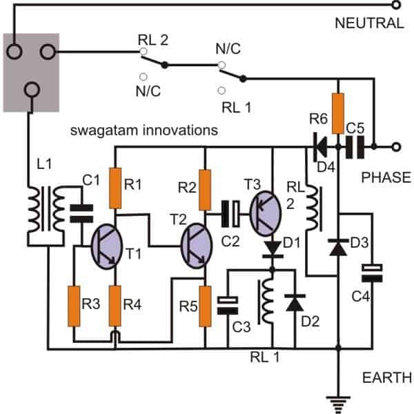
As shown in the diagram, a simple bootstrapped amplifier network forms the main sensing stage of the unit. Transistors T1 and T2 along with the associated passive components are wired up into a small two stage amplifier.
The introduction of R3 becomes very crucial as it provides a positive feed back to the input making the circuit more stable and respond to minutest input signals.
The inductor L1 basically has two windings, the primary which is connected to the earth point of the socket has less number of turns, the secondary winding has six times more number of turns and is integrated to the input of the circuit via C1.
The role of L1 is to amplify any AC induced into its primary winding which can only happen in case of a leakage through the body of an appliance connected to the socket.
The above amplified leakage voltage is further amplified to a level enough to activate RL1, instantly disabling the input to the appliance and indicating the earth leakage fault.
Capacitor C5 along with D3 and C4 forms a standard transformerless power supply to power the circuit.
D3 performs a dual function of rectification and surge suppression. Interestingly the main earth connection itself becomes the negative of the circuit instead of the neutral line.
Also since RL2 is directly connected to the supply across the positive of the circuit and the earthing, simply means that if the earthing becomes weak or disconnected, the relay will deactivate, cutting off the AC mains to the appliance, so it effectively indicates the health of the earthing and safeguards the house from faulty or missing earth connections.
ELCB Circuit Parts List.
- R1 = 22K,
- R2 = 4K7,
- R3 = 100K,
- R4 = 220E,
- R5 = 1K,
- R6 = 1M,
- C1 = 0.22/50V,
- C2 = 47UF/25V,
- C4 = 10uF/250V,
- C5 = 2UF/400V PPC,
- T1, T2 = BC 547B,
- T3 = BC 557B,
- Relays = 12V, 400 Ohm, SPDT,
- All Diodes are = 1N4007,
L1 = Coil wound over a bobbin used normally with E-cores (smallest size,) begin winding 50 turns of 25 SWG wire first, tie it up and solder it to produce the primary terminals at one side of the bobbin.
Now using 32 SWG copper wire, wind 300 turns over the primary winding, as before tie the ends to the other side of the bobbin by soldering. Insert and fix the coil within the E-cores. Secure it tightly using PVC tape
How to Make a Homemade Earth Leakage Breaker (ELCB) Unit Using IC 324
An earth leakage circuit breaker is a safety electrical device used for monitoring current leakages through the “earthing” terminal and switching OFF the mains when this leakage exceeds a certain dangerous level.
Introduction
Normally electromechanical concepts are employed for making these devices, however here we will see how an ELCB can be made by using ordinary electronic components; we will also see why an electronic counterpart is more efficient than the commercial electromechanical units.
There are three versions through an electronic ELCB can be made, the first uses a relay for the switching actions, the second idea incorporate a Triac and the third concept employs a SSR or a solid state relay for the required implementations.
For all the above concepts, the triggering feature remains the same, through an input inductor stage.
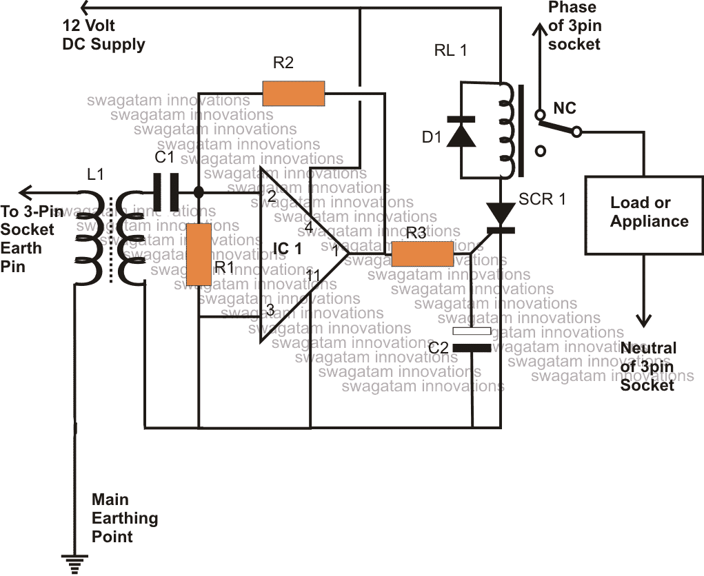
ELCB Circuit Using Relay
Looking at the figure we can see that the entire circuit is concentrated around a single Opamp from the IC 324. The op amp is configured as a high gain inverting amplifier.
The op amp is configured as a high gain AC amplifier and its sensitivity can be adjusted by varying the value of R2, increasing its value increase the sensitivity of the circuit.
Any minute AC signal that may be present at the inverting input #2 of the IC is picked via the coupling capacitor C1 and instantly amplified by the IC.
A small inductor transformer is wired across the above input of the IC.
The primary of the inductor is connected to the wire which finally terminates to the earthing terminal or the pin of the various 3-pin sockets in the premise.
The transformer can be an ordinary output transformer used in small radio receiver’s output amplifier stage.
In case of a leakage, the leaking current passes through the primary winding of the inductor and gets stepped up at the secondary winding.
The stepped up induced AC is immediately sensed by the IC input and further amplified to the desired levels, so that the SCR switches in response to the triggering.
The SCR, due to its inherent property instantly latches and pulls the relay into conduction.
The relay conducts and switches OFF the mains power to the three pin sockets, switching of the appliances and thus eliminating earth leakage conditions
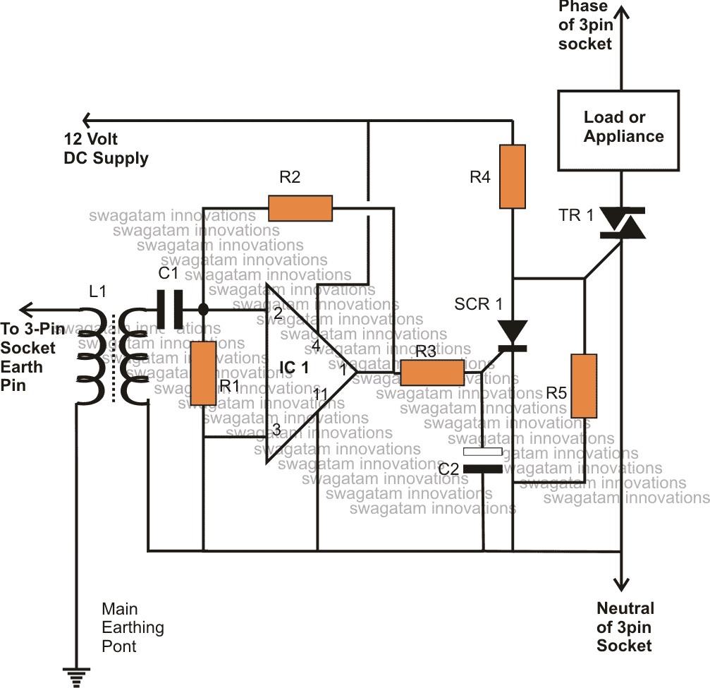
ELCB Circuit Using a Triac
The above circuit can also be implemented using a Triac, everything remains the same, except the relay stage, which now gets replaced by a Triac.
During normal conditions the IC output remains switched OFF and the triac is allowed to conduct and operate the load.
However the moment a leakage is sensed, the IC output goes high, which triggers the SCR and latches its anode to ground.
This inhibits the gate current to the triac which instantly stops conducting, switching OFF the load and rectifying the unfavorable conditions.
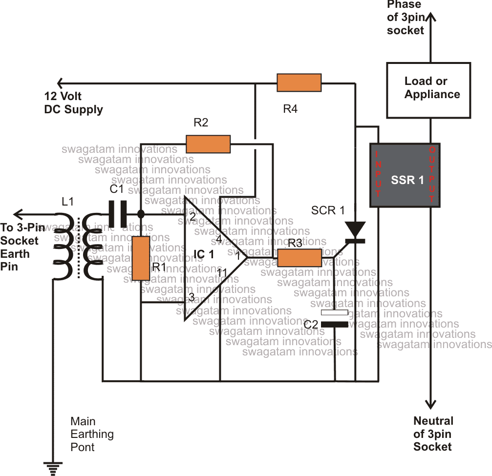
ELCB Circuit Using an SSR or Solid State Relay
Mains operated SSR devices are nowadays being effectively employed for switching mains operated loads more efficiently than relays and since these are electrically isolated and solid state in nature, becomes more desirable than the conventional switching devices like triacs and relays.
Here, as long as the conditions are normal, the SSR is able to derive the required input triggering voltage from the circuit.
However the moment an earth leakage is anticipated, the circuit triggers the SCR which in turn chokes the SSR input trigger to ground.
The SSR instantly stops conducting, implementing the intended actions by tripping the load and prevents any possible hazard.
Parts List
- R1 = 100K,
- R2 = 1M,
- R3, R4, R5 = 1K,
- C1 = 0.01uF
- C2 = 100uF/25V
- L1 = ordinary small output transformer as used in transistor radios.
- SCR = BT169
- Triac = BT 136 or higher current type
- Op amp = ¼ IC324
- SSR = As per user specs.
- Relay = 12V, SPDT
Warning: I have not tested these ELCB circuits practically, therefore it needs a thorough testing before a practical implementation. All the circuits involve mains AC which can be lethal if touched in an uncovered and switched ON condition.


Questions & Answers
is above circuits are work as same like ELCB circuit breakers, which trigger when human body get electrical shock ? if not then how to make that type of circuit ? Because i need it for Electric Water Geyser.
No, the above circuit will not prevent shock…You can get more info in the following post:
https://www.homemade-circuits.com/how-rccb-works-with-circuit-diagram/
Both circuits is incorrect Please, Please do not build this circuit for humans and any living species, The earth line cannot be monitored only the supply, is there an imbalance in the live or neutral trip the mains. The power into the circuit is not equal to the power out of the circuit, thus it’s going to EARTH.
Monitor the difference, 20mA, then if so trip the power, show me a transformer winding to do this, 3 windings 2 in/out 1 to trip.
Do you understand the difference ELCB and RCCB. This is not an RCCB circuit, it is an elcb which will disconnect mains in case there’s a mains leakage and the earthing is not good. This is not intended to disconnect when a human gets an electrical shock.
That said I have only presented a concept which might need improvements.
Which SSR is used.
AC to DC
DC to AC
DC to AC
In elcb circuit diagram using transistor, what is the value of C3. Please comment.
you can use 100uF for C3
Hello, I have shown a sensing transformer in the diagram, if you are also using the same concept, you can connect a calculated load resistor across the secondary side of the transformer, the residual current could be measured across this load resistor.
IF i have a 12Volt DC device and the 12V DC supply shorts to Ground will this trip a convenional household earth leakage device ?
No, it may not, the potential must be over 50 V or 100 V to trip the ELCB, and with a few mA current
Sir,
Elcb circuit using Transistors having 5 capacitors.
Some of DC and Some AC rated.Could you please mention polarity of all caps.
Thanks
Raman
Raman, polarity of the electrolytic capacitor symbols are clearly shown with their black and white box colors, non-polar capacitors are without any polarity.
Thanks Sir.
Still having confusion.
One cap both legs/termnals are black.
Another cas one termnal white and second leg is white,what does their means.
Raman, the only black capacitor symbols represent non-polar capacitors such as PPC, or ceramic types, while the black/white types indicate only electrolytic types which are polarized. White side leg represents the positive lead, black is the negative lead.
Thank you very much Sir
You are welcome Rajat!
Curious to know more about Electronic Operated ELCB employed in modern Home Shower Water Heater.
Sir,
As you wrote on diagram to connect 12 volt DC.
Sir, at which point positive and which point negative will be connected?
Thanks a lot Sir,your prompt response is highly appreciated.
No problem!
Ramesh, + will on the top R4 line, and negative will be on the neutral line
Please help me with abstract of this simple earth leakage circuit breaker i need it please.
sorry sehu, writing abstract can be quite time consuming and won’t be possible for me at this moment.
hello ..
whats the value of c3 ?
thank you bro
you can use 100uF/25V
Hello..swagatamsir.
I want to use this circut for ur another project high volt ignition coil…i want to blow siren instend of switch off done with above circuit..can I use this circuit for my fencing ..and if it is possible than which type of change I have to make in above circuit..
Hello Sanjay, yes it's a viable idea you can try but make sure you try the above circuit separately first on your work bench…once it's confirmed then you go for the final implementation.
hello Neha, it will do if it is able to amplify small mV AC to at least 2V AC…for example a small audio-output type of transformer will work here
tanx for ur replay
PLS,, is the C1 polar capacitor or non polarized and the is no C6 in the circuit as you have named it
I have corrected the parts list, please check it out now…
HELLO, Pls is the circuit working efficiently because i wll like to use it as my school project..thanks in advance..
It has not yet been tested practically, however as per my mind simulation there's no way this cannot work if built correctly….the trafo is criucial here
It will switch off the load whose body may be leaking current on the earth line.
this circuit will not protect from under/over voltages.