The 5 simple fastest finger first indicator circuits presented here can be used for indicating which candidate was the first to press the answer button out of the 4 participating candidates in a quiz contest.
We all have probably seen the famous game show "who wants to be a millionaire" and many similar quiz shows, where in the initial stages a few of the participants are asked to go through a small test, the participants are asked a question, and the member who answers it first by pressing the buzzer is given the opportunity to occupy the "hot seat".
Well everybody might not be as lucky to get into such game shows, but you can certainly enjoy making and playing with this little fastest finger first decider circuit right in your home. These circuits is very simple, utilizes some ICs and some LEDs.
Design#1: Using SCRs
Originally intended to be used as a quiz controller, this straightforward priority switch circuit allowed four participants to respond to questions in order of pressing the button first.
Design Criteria
In this case, there are clear design criteria to take into account. The push switches have to be placed far from the main unit, and everyone ought to be able to view an unambiguous display of which switch won.
A straightforward reset feature should also be included, and the circuit must be absolutely honest; or else you risk having a group of disputable players before the contest ever starts!
This device latches and illuminates the appropriate LED by switching the first signal it receives from any number of inputs (in this example, four, however the circuit can be easily upgraded to include any number of contestants).
To switch on a much larger display structure, or perhaps to illuminate the initials of the participants in front of them, the LED might be substituted with a relay or opto-isolator, if necessary.
How the Circuit Works
Each thyristor switch in the circuit is made up of an LED, a high value gate resistor, and a usually open push button switch. It is possible to arrange them in any number of parallel configurations; the circuit shown employs four.
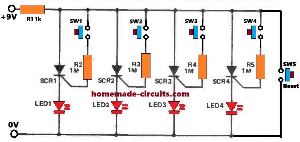
The circuit is limited to provide just the minimum amount of current—roughly 13 milliamperes for an LED supply—for one module to function.
Each of the connections are created after the power-resisting resistor R1, which is connected to the positive supply.
Power is sent via the gate resistor when just one toggle switch is closed, turning on the module. From the moment as it begins to conduct, the voltage across the other modules drops to around 3V.
Not enough power is available to switch other switches even when they are pushed.
Switch SW5 can be pushed to unlatch the thyristor by shorting the 13mA to ground, resetting the circuit.
Design#2: Using IC 74122
In a 'professional' quiz game set up, we may require some form of electronic detector for accurately detecting the fastest candidate pressing the buzzer button and the first candidate to answer an asked question.
The simple fastest finger first circuit using IC 74122 shown below is designed to implement the proposed task.

Circuit Description
Push-button S5 is one button that is controlled by the quiz master.
As long as the quiz master keeps this button depressed, all the LED indicator stages remain disabled. The moment he releases S5 all the remaining circuits and the associated press buttons become active.
The candidate who presses one of the assigned buttons (S1-S4), it triggers the monostable (IC1 -IC4) stage connected with that button.
The monostable switches ON the respective indicator LED and at the same time blocks the other three monostables by means of N1.
The period for which the monostables remain disabled is around 8 seconds, after this delay the indicator lamp switches OFF allowing the other candidates to resume the fastest finger first game. The quiz master has the power to reset all monostables whenever he wants it, or when it is essential to 'override' button S5.
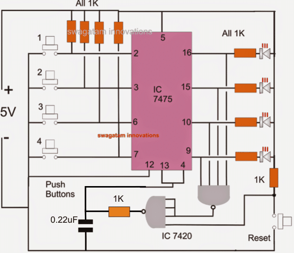
Design #3 Using IC 7475
In the third design four push-to-ON type of switches are placed at the input of the IC 7475 which is a 4-Bit Bistable Latch with Complementary Outputs.
The button which is pressed first, triggers the relevant output of the IC 7475, which in turn prompts the IC 7420 to instantly deactivate the other inputs from the other push buttons, rendering the whole system inactive, except the one which had the first trigger through the push button.
This output concerning the triggered latch illuminates the relevant LED, indicating the button number which was pressed first.
The is a simple game circuit which can be built by all electronic hobbyists and also school kids.
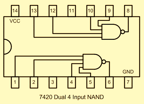
Pinout Details of IC 7420
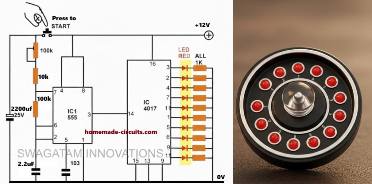
Design#4: 8 Contestant Fastest Finger First Circuit Using IC 555
The main function of our fourth fastest finger first circuit is to reveal which of the potential eight participants dialed in first, so that person can respond to a question. The competitors receive an auditory signal from it to tell them to halt trying to ring in.
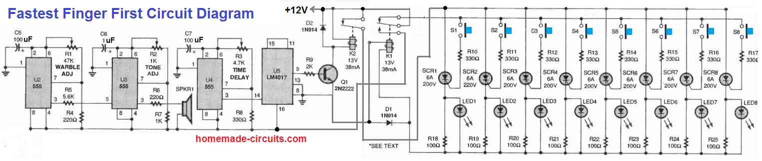
The circuit moves quickly, almost eliminating the possibility of a deadlock between two or more competitors.
The eight silicon-controlled rectifiers in the circuit conduct when switches S1 through S8 are closed, activating relay K1.
This then disables power to the switches and activates the audio oscillator/timer portion, making it difficult for anybody else to call in. The voltage drop across the equivalent 100 ohm resistor causes the competitor's LED to turn on.
The audio oscillator, which generates a high pitched sound, is made up of the timers U2 and U3. Potentiometers R1 and R2 can be adjusted to change their frequency.
The 4017 decade counter/divider, U5, and the 555 timer U4 make up the timer part. By varying the potentiometer R3 causes the 555 IC to produce the timing pulses which is fully adjustable.
The transistor Q1 switches on and K2 is activated once pin 9 of the 4017's timer sequence achieves a high state. This resets the circuit.
Design#5: 3 Competitor Fastest Finger Response Monitor Circuit
Our fifth circuit design creates a simpler, three-competitor fastest finger first monitor circuit by combining NAND gates and SCRs.
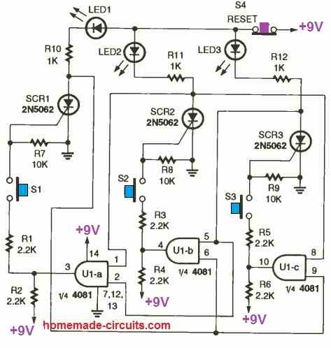
In this circuit, we use a 4081 quad 2-input AND gate, which controls the logic between the SCRs.
Remember that if any input of an AND gate is low, the output will likewise be low; hence, an AND gate cannot have a high output if any of its inputs is low.
When the circuit is reset (through S4), the three SCRs are turned off, each AND-gate input is high, and the outputs of the AND gates are also high.
The three gates' outputs are high enough to provide the gate current required to switch on each SCR. If S1 shuts first, SCR1's gate is activated and LED1 is lit by the high output of U1a applied through R1 to the gate.
The inputs of U1b and U1c, which are connected to the anode of SCR1 at pins 6 and 9, respectively, are pushed low at the exact same time. Because of this, SCR2 and SCR3 have low output and cannot be switched on.

Comments
sir,
how to contact you.
Kanungo, You can get in touch thru comments, right here. I will try my best to solve your questions….
Great website!!!
Regarding Design #1 (using SRCs), can you provide an SRC part number as well as the resistance for R2-R5?
Thank you for your question,
SCRs can BT169, and the resistors can be as given in the diagram.
https://www.homemade-circuits.com/bt169-scr-datasheet-200-v-0-5-a-scr/
hi Sawgatam, can you please help me with a circuit design, whereby a switch is at each bed side patient, to alert the nurse for assistance, total of 8 patients, one switch per patient each in different rooms. the nurse in a separate “control room”. so a small buzzer and a led light to identify the patient who requires help.
Hi Ramesh,
I think have a related post available in this blog, you can checkout the following post:
https://www.homemade-circuits.com/hospital-room-call-bell-circuit/
hi Swagatam, thank you so very much for your speedy response, i will check out the circuits
Thanks Ramesh, I am glad to help!
could you modify this design to work with sound as an activator not a push button, im looking to create a “who fired first” for quick draw shooting so need a system that will pick up the bang of the first gun to fire and light its light disabling the opponents light, then auto reset after say 15sec.
Yes that may be possible. You will need 4 separate sound activated relay circuits, and then integrate the relay contacts with the relevant push switch contacts.
You can try the following sound activated relay circuit as an example:
https://www.homemade-circuits.com/wp-content/uploads/2022/04/clap-switch-staircase-lamp.jpg
Please ignore the LED bulb and its associated wiring.
HI
Hi friend
Could this combinations below be correct?
(7420) 1-2-4 to 8 (7420)
(7420) 5 to (reset button)
(7420) 6 to 13-4 (7475)
(7420) 9 to 9 (7475)
(7420) 10 to 10 (7475)
(7420) 12 to 15 (7475)
(7420) 13 to 16 (7475)
Great thanks ヅ
Yes that looks OK to me.
Hi friend
Nice and simple circuit, the “SECOND”…
i would like to make it…
But i cannot the numbering connection of IC 7420 to others?
greetings ヅ
Thanks friend, I have updated the pinout details of the IC 7420 at the end of the post, you can connect them accordingly.