An impressive 120 watt amplifier circuit can be built by cascading a couple of TDA 2030 IC in a bridged tied load (BTL) configuration and through a few current boosting transistors.
Advantage of a BTL Amplifier Topology
The main objective of a BTL configuration is to enable a two way operation of the load which in turn helps to increase a two fold increase in the efficiency level of the system. It's equivalent to a full bridge network which we normally find in inverters.
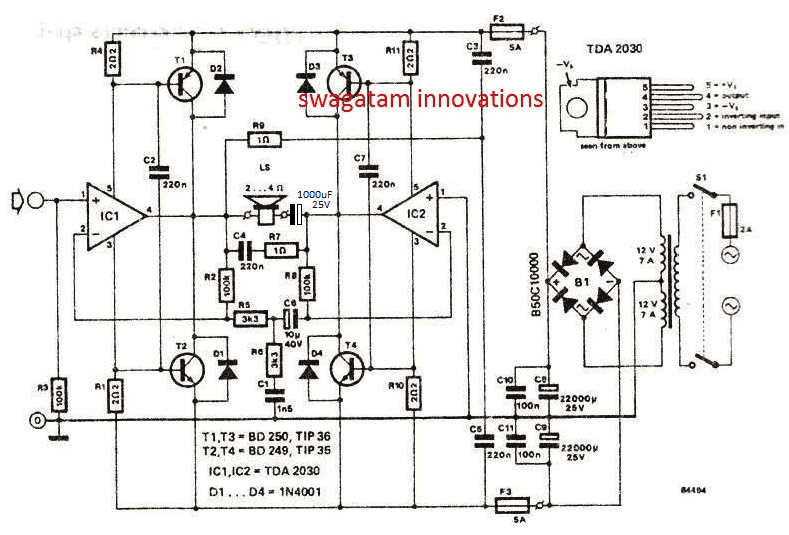
Image Courtsey: Elektor Electronics
The complete circuit diagram for the proposed BTL 120 watt amplifier circuit using two TDA 2030 ICs can be seen in the above diagram.
Circuit Operation
IC1 and IC2 are the two TDA2030 ICs rigged in a bridged tied load configuration which means the these two IC s now conduct in tandem in response to the high and low amplitudes of the input frequency and drive the loudspeaker in a powerful push pull mode.
For example when IC1 output may be delivering a high output to the speakers, IC2 simultaneously would be delivering a low output and vice versa enabling the required push pull action on the loudspeaker. This means the loudspeaker would be alternately operated with maximum positive and negative supply levels, causing the loudspeaker to work with double efficiency level compared to the normal amplifiers which are not BTL based.
The BJTs T1---T4 are included to boost the current level of the amplifier upto the specified 120 watt RMS, since the IC1, IC2 alone wouldn't be able to do this.
The NPN/PNP output BJTs also complement the BTL topology and help the ICs to achieve the specified amount of power on the loudspeakers.
The various resistors and capacitors around the speaker are introduced to suppress and filter the final outcome on the speaker, and to produce a clean and distortion free audio on the speaker.
Dual Power Supply for the Amplifier
The power supply for this 120 watt BTL amplifier using TDA2030 ICs is derived from a 12-0-12V / 7 amp transformer. whose output is rectified using a bridge rectifier and filtered using the indicated capacitor C8---C11.
The power supply produces a dual +/- 20V / 7 amp output which is mandatorily required for most BTL based amplifier circuits.

Comments
I have built d this same cct with all d component stated but I found out that on d connection of d speaker something is wrong . guess what happened I smell magic smoke through the speaker and a lot of heat was been generate on each heat zinc so I try to measure voltage and it’s 15v+… what I did was I added a cap 1000uf series with d speaker. that’s my solution and it work. or any better suggestion sir ?thanks to great icon swagatam
yes I think you are right. because normally when we operate a single IC we employ a series capacitor otherwise the speaker and the IC can get shorted.
I will update the circuit soon with a capacitor…thank you for this useful information.
Hi Swagatam, hope you are doing well. BTW is this amp truly a 120-RMS or 120-Watt, lastly I can replace the two TDA2030 with a TDA2050. Thank you. Regards.
My pleasure!!!
Thank you Swagatam, you are a great man. Regards.
OK great, no problems then!!
Yes it is. I have checked their datasheets and they are almost same, the only difference is TDA2050 has a higher input voltage and more wattage power on the output. Some few months ago I have replaced TDA2030 with TDA2050 on my old PC woofer and it still works like a charms:) Thank you. Regards.
You are most welcome Lima!! hwoever I am not sure whether TDA2050 is pin to pin compatible with TDA2030 or not.
Thank you so very much for your time and help, greatly appreciated:) OK this will be my project for this season:) but I will be using TDA2050 instead of TDA2030. Regards.
Hi Lima, it is 120 watt RMS, because along with the IC the load is also handled by the external BJTs, which allows the design to run the specified amount of power continuously without any problems.
please mention the wattage of the resitors and the voltage raings of the condensors along with a pcb for the 120w amp
non-polar caps can be all 100V rated and PPC type.
when not mentioned, you can always assume them to be 1/4 watt 5% CFR
I would want to use it for car audio since its single railed. Normally removing the transformer and the power supply stage should do the trick but I realize in this circuit the transformer center tap has made a few connections, IF I was to to run this from just a 12v battery that means I could just replace the center tap connections with battery negative?
No that may not be possible, you will have to use two 12V bats in series, and use the series joint as the ground for the amplifier, this will replace the center tap rail of the trafo.
and the +/- from the battery can be used for (+) and the (-) supplies of the amplifier.
Was this circuit tested
yes 100% tested