The post narrates a simple yet highly accurate adjustable 1 to 10 minute timer circuit with display. The idea was requested by one of the dedicated readers of this blog.
Technical Specifications
I am trying to build a circuit to help me with giving speeches. I have a bunch of parts already and I would like to use them if possible. I want it to have an On/Off switch to power the circuit and a Start/Stop button as well as a Reset button.
I would like for it to light a Green LED after 5 mins, then turn off the green LED and light an Amber LED at 6 mins, and then turn off the Amber LED and light a Red LED as well as sound a buzzer at 7 mins.
I would also like to have a seven-segment display show the elapsed time. Let me know haw feasible this would be. Thanks.
The Design
In the shown 1 to 10 minute timer with display circuit, IC 4060 is configured as a 1 minute clock generator which is acquired at its pin#3.
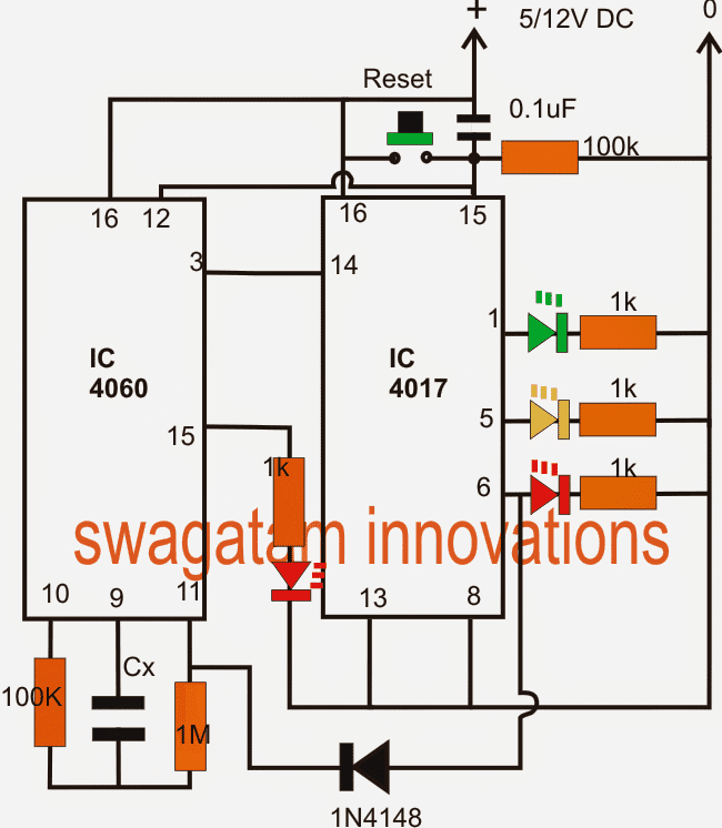
The IC 4017 is wired in its ususal decade counter mode wherein its outputs shift a logic "high" across its pin3 to pin6 in response to every single minute pulse by the IC 4060 at its pin#14.
As requested three LEDs are positioned for indicating the elapsing of 5 minutes, 6 minutes and 7 minutes in sequence across the pin1,5,6 respectively, with the relevant selected colored LEDs.
For setting up the IC 4060 with 1 minute intervl at its pin3, we initially use a randomly selected low value capacitor for Cx and then note down the interval at pin3 for this capacitor.
Once the interval is known, the value of Cx for achieving 1 minute time may be calculated with the following formula:
Cx/Cr = 1/Rm
where Cx = required value, Cr = random value capacitor (in uF), Rm = time interval noted from Cr (in seconds)
The reset button at pin15/12 of the ICs can be used for resetting the circuit to original state.
Once the final selected interval is elapsed, the circuit latches itself and freezes by supplying a "high" from the relevant IC 4017 output to pin11 of IC 4060.
The red LED at pin15 of 4060 IC indicates the counting process by blinking the connected LED until the pin#6 of IC 4017 goes high.
The proposed circuit can be used for indicating any time interval from 1 to 10 minutes by using all the outputs of the IC 4017.
For getting different ranges of time intervals across each pinout of the IC 4017, the IC 4060 clock can be set with the desired time ranges, for example 2 minutes, 5 minutes, 40 seconds etc.
This 1 to 10 minute timer circuit when used along with a 7 segment display circuit as illustrated below could consume around 60mA current so probably a ac/dc adapter would be more preferable than a battery.
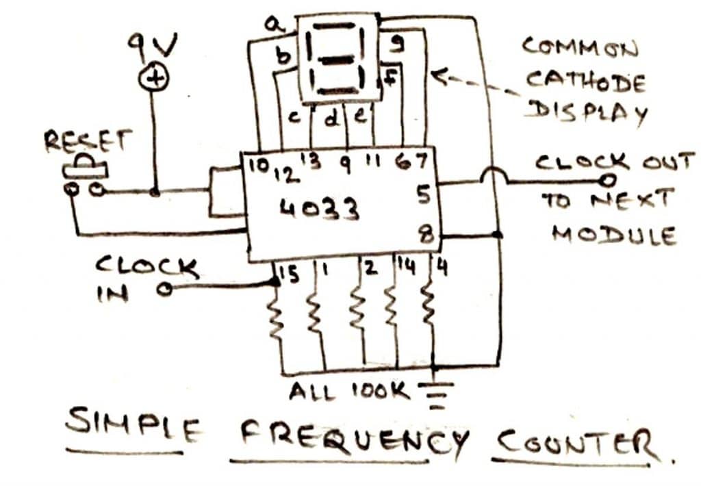
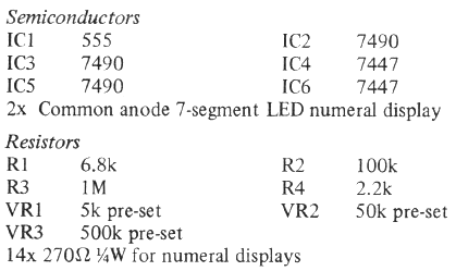
Adding a 7 segment display to the above circuit
A simple pulse counter circuit using the IC 4033 shown below can be used with the above circuit for displaying the elapsed minutes.
The clock IN pin should be connected with pin3 of IC 4060.
The circuit will faithfully display the elapsed time in minutes right from 1 to the last selected minute output.
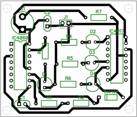
PCB Layout
1 to 10 minute timer using just two transistors
The above designs look unnecessarily complex. Because the same application can be efficiently implemented through a 2 transistor circuit as shown below:
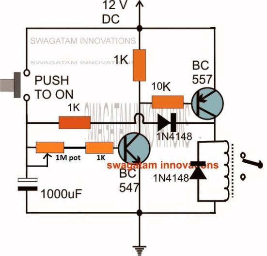
When I initially designed this, it was without the 1K/1N4148 feedback link, which actually made the design rather inaccurate with its timing cycles.
This was because of the inconsistent discharging of the 1000uF capacitor which caused inaccurate timing outputs for each subsequent timing cycles.
I realized the issue and solved it by adding the 1K/1N4148 feedback link across the BC557 collector and the 1000uF capacitor positive pin.
This ensured after each timing cycle when the BC557 switched OFF allowed the capacitor's residual charge to completely discharge via the 1K/1N4148 link and the relay coil.
This in turn allowed perfect accuracy for the capacitor charge/discharge cycles and produced uniform, consistent timing intervals for each subsequent cycles.
Simple 10 Minute Timer using an FET
The below shown 10 minute simple timer is a form of enhanced Schmitt trigger, using a combination of an FET and a BJT.
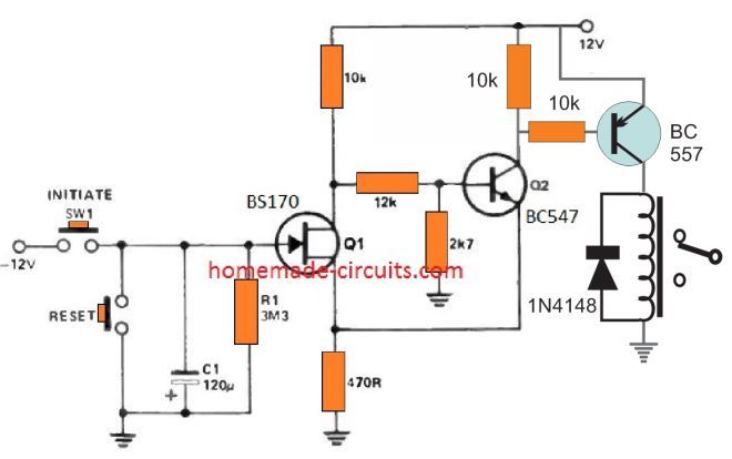
In the stand-by powered mode, the FET Q1 is in the switched ON condition, the BJT Q2 remains switch OFF, and the relay will be deactivated in its N/C position.
As soon as the timer is initiated by pressing the "initiate" switch, the capacitor C1 begins charging rapidly with the -12 V, which cuts off the FET and switches ON the BJT.
Now, when S1 is released, C1 begins slowly discharging through R1, until the potential across C1 drops to Vp of the FET.
At this instant Q1 turns ON again, and Q2 BJT turns OFF, reverting to its original standby state. The relay now deactivates again
Much longer delays can be achieved by selecting an FET with lower Vp than 1.5 V, and higher values of C1.
The only drawback of the design s that, it works with a dual supply voltage.


Comments
I need a simple and robust adjustable timer circuit, to controlling the gasflow on a CO2 welder- The delay funktion is needed to let the gas flow a couple of seconds after welding power is cut of – to let the metal”dry” or els it will turn to popcorn, in a very fast ocidation process , coursed by the intens heat- The control power is 24 V, and 1-3A is very ok to a small selenoide with a gas-vent- I have seen a lot of those diagrams, but timing-1-5 sec and 24V is’nt present- If I could talk you into a adjusting of one of the more simple diagrams- I’m a bit rusty- and it don’t have to be that precice- and must not be to space- consuming-something like5x10 cm and with a small coling devise- a piece of copper or alu- The velder content a effective blowermotor, constructed for coling a bunch of 50A diodes on very large casted alu-profiles for extended coling- Thank you for simple constructions, and a very understable lingo !!
So basically you want a solenoid to remain switched ON for 1 to 5 seconds once the input power is switched OFF, right? This can be perhaps done with a simple transistor circuit.
I would like to incorporate your 2 transistor timing circuit into my simple motorcycle alarm which is triggered by a mercury switch when the bike is moved from the side-stand position (leaning) to the upright position. Currently if triggered, the alarm will keep sounding until it is either turned off (keyed switch) or the battery dies!! As my bike does not have a kick start I would never want a dead battery.
What I would like to ask is how to change the circuit so that is stays on for 3 to 4 minutes rather than have the variable pot?
The two transistor circuit will not work for your application because the indicated push button needs to be pushed only momentarily and released. If it is replaced with a mercury switch, it will remain triggered permanently ON and the alarm would never turn OFF.
Instead I would recommend the 3rd circuit from the following post. Here. you can replace the push button with your mercury switch and get the intended results.
https://www.homemade-circuits.com/how-to-make-simple-timer-circuit-using/
Greetings, and thanks for the prompt reply.
After some consideration I thought I might be able to combine my present circuit with your two-transistor one where my secondary relay would disconnect the mercury switch when activated. However, after further thought I realised that once the timer had finished then everything would be reset and if the mercury switch was still on the ON position then the alarm would be sounding again.
Unfortunately if I go for your suggested circuit I would have a couple of problems: (a) I live “in the provinces” in the Philippines and the components would have to be ordered on line (expensive) and (b) there is not much space on my bike for any additional wiring
But many thanks for your input and wish me luck!
OK, no problem, hope you find a proper solution soon.
Thank you, but why were my links deleted?
Greetings Mr. Swagatam.
I built a timer up to a 10-minute timer using only two transistors.1 to a 10-minute timer using only two transistors. That is the involvement that I just needed. But with the feedback you made there, I’m not doing well. Through the diode in the feedback and through the relay coil, the capacitor is still discharging. I discarded the resistance and the diode.
Thank you for the tutorials and stay with regards. Marian Tkáč
Thanks Maraian, Glad you could build it, however without the 1N4148 and the 1K feedback the time delay will not be consistent and identical for each of the cycles
Yes, 10secs lag
You can add a capacitor across base/emitter of the relay transistor. The value can be anywhere between 100uF and 1000uF depending of the base resistor used.
Good day sir, I have a 1min on/off timer using ic4060 and a relay. Is it possible to have a 10secs pause or delay between on and off of the relay.
Do you mean to say the relay must lag 10 seconds behind for every logic output from the IC?
Dear sir,
I have a light chaser machine I need a time interval of 20 sec between every bulb so pls help…. I have a local market chaser mchine…pls help with a diagram
Dear Sameer, it seems you did not tick the "share" option, therefore the images are not opening for me….please make it public and tick the "share" box
Dear Sir,
for images pls find the below link
https://drive.google.com/open?id=0B6nYqoqIyNBscGltSmpNeDhCQUU
https://drive.google.com/open?id=0B6nYqoqIyNBsUjBUZFgtakZfamc
https://drive.google.com/open?id=0B6nYqoqIyNBsZ2lNRWVjTjhDUWM
Sir i m not able to upload image here …so any other way to send image to you..
I wll help out with image
Dear Sameer, you will need to open the unit and locate the oscillator stage and then adjust the values of the relevant RC components for achieving the delay….if you could show me the internal snapshot I would be able to probably help you out…
Make the circuit that's shown in this article:
https://www.homemade-circuits.com/2012/04/how-to-make-simple-programmable-timer.html
this becomes your 8sec/1 hr timer.
once you do it successfully next we'll proceed with the 12hr timer integration.
Dear Guru,
If Guru has already circuit and the code, please send me by e-mail ?
Many Thanks and Regards,
ilman.gumilar@gmail.com
sorry Gumilar, i do not have the code right now, if i get it will surely let you know.
Dear Guru,
Can we make it by Arduino Uno ?
Thanks,
Gumilar
Dear Illman,
yes it can be used.
Dear Guru,
1. Can we set the duration of the Hours : Minutes : Seconds => 0 to 9h : 0 to 59m : 0 to 59s -> flexibly by using the up and down keys and display on 7 segment display as the duration of the timer ?
2. Having determined the duration of the timer can be made button start / stop ?
3. If the start button is pressed, the display will count down to 00:00:00 ?
Thanks,
Gumilar
Dear Gumilar, it could be done but the circuit will involve many ICs and a relatively complex circuitry.