Today the traditional wired type of doorbells are gradually getting obsolete and are being replaced by the advanced wireless type of doorbells that are easier to install due to their hassle free set-ups. A simple wireless doorbell circuit is discussed in the following post which can be constructed at home.
Written and Submitted By: Mantra
303MHz TRANSMITTER with 32kHz Crystal
The initial circuit we are going to explore has a 32kHz crystal to crank out a tone which means that the receiver is unable to false-trigger.
We could perhaps experience a fault with the commercial RX-3 circuits every 2 minutes, this might be due to the chip detecting a frequency of 1kHz or 250Hz from the environment disturbance received by the RF transistor, to turn on an output.
That's exactly why the RX-3 receiver chip is untrustworthy. A 32kHz is a much better frequency to identify because it does not get rattled from environment resonance.
The functionality of a 303MHz circuit has been covered in this project WIRELESS DOORBELL.
We are not going over how the circuit works but explain the importance of some of the components and how they effect the range.
The Wireless Doorbell transmitter and receiver circuit are incorporated below:
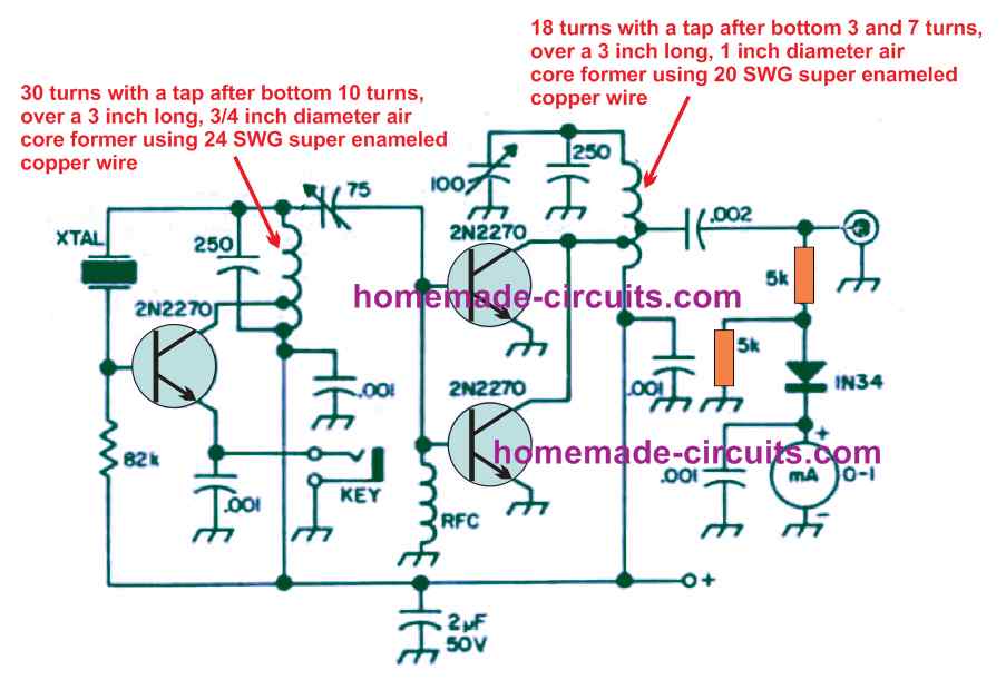
All Transistors are 2N3563, the U shape coil is a single half turn using a 1mm copper wire with 5mm diameter
The most fundamental constituent is the transistor.
An excellent transistor is critical in the RF phase and the Japanese transistors are undoubtedly suits this objective.
The transistor employed in the 303MHz oscillator possesses an optimum frequency for the functionality of 1,000MHz in this most assuredly is where the gain is equal to "1," therefore we would like a transistor to have a unique gain at 300MHz.
A BC 547 transistor is not going to function at this frequency as a result now we have considered a good choice a 2N 3563 that may be inexpensive which enables it to work with up to 1,000MHz. requirement papers when dealing with these transistors:
303MHz TRANSMITTER using 4049 IC
The following circuit works by using a CD 4049 IC to churn out the 32kHz frequency and four gates in parallel to transform the oscillator transistor on and off at the tone-rate.
An individual gate will not likely possess as much as necessary performance to suck the emitter to ground, nevertheless 4 gates will certainly bring along the emitter in close proximity to 0v rail.
It ought not be at specifically 0v as the 6p would not possess a direct impact in sustaining oscillation.
The IC bears 6 gates just in case an input is probably above mid rail, the output moves LOW.
Any time the input amounts to slightly below middle of the rail the output scales HIGH. The space between detecting a low and a high might not be massive as well as the gate will certainly pick up receptions referred to as "analogue signals."
However to obtain the oscillator circuit to startup, a resistor is positioned between output and input.
This will likely generate an oscillation at the maximum frequency for the gate roughly 500kHz to 2MHz..
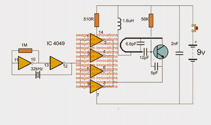
All Transistors are 2N3563, the U shape coil is a single half turn using a 1mm copper wire with 5mm diameter
In case an additional gate is included along with a crystal hooked up between the output as well as the input, a "fight" transpires between the transmission coming from the 1M and the rate of recurrence transferred by the crystal.
Considering that the crystal possesses a reduced impedance as compared to the 1M, it accomplishes a more substantial signal to input pin 11 along with the 2 gates function at the frequency of the crystal.
The precise characteristics of the correct way the reception from the crystal overtakes the signal administered back from the 1M resistor is not critical in spite of this providing you can contemplate the first gate starts out to rise in frequency from nil, every time the signal reaches 32kHz, it commences to initialize the crystal which in turn forces the signal on the reverse side and into the input pin of the first gate.
Each transmitters churn out the identical outcomes, a 303MHz carrier with a 32kHz modulation (frequency - despite the fact that we are unable to perceive sound in this frequency). Each possess the matching spectrum.
The oscillator coil is furthermore the radiator of the signal as well as the 1.5uH inductor on the "centre tap" of the coil is often as high as 10uH or as little as 1.5uH, with minimal variance in output.
The frequency might well need to be realigned somewhat if the inductor is modified.
We transformed it for a forty turn air-would coil working with.25mm wire on a 2mm former. This amplified the distance by one metre.
Inductor Specifications
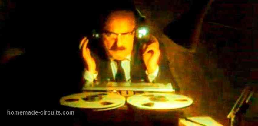
A sixty turn coil enhanced the range an additional 3 metres once it was subsequently expanded it added to the impact of the antenna. The pair of photos below exhibit the positioning of the air-inductors.
40 turn coil swapping the 1.5uH inductor. Sixty turn coil expanded to multiply the range of the wireless transmitter
All Transistors are 2N3563, the antenna coil is 2.5 turns of 1mm copper wire over a 5mm variable slug assembly
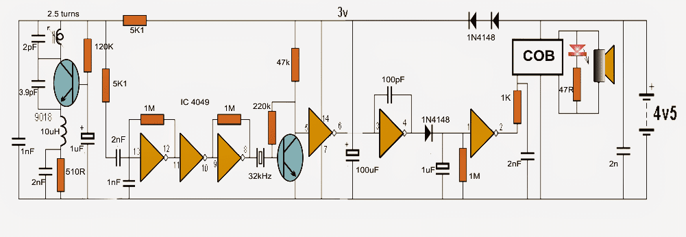
303MHz RECEIVER
This doorbell is cheaper than $8.00 therefore it is impossible to get the components independently for lower than that.
This sort of circuit formulates an excellent groundwork for exhaustive study. It is possible to investigate the RF side of the circuit not to mention the high impedance segments.
Each gate includes promoting an extremely high gain and by applying a 1M from output to input the gate is saved in a state of stimulation, oscillating at approx 500kHz, in the event hardly any other parts encompass the gate to manage the frequency.
This could be formulated to retain the gate dynamic to ensure that the tiniest signal is going to be processed.
When it comes to the gate between pins 13 and 12, the 1n capacitor between the input and ground lessens the frequency significantly, in addition to the impact of the 2n2 as well as 5k6 resistor.
The 2nd and 3rd gates straightforwardly improve the amplitude of the signal and never render any specific version of elimination of undesired receptions.
The consequence is an entire amplitude signal at the left-side of the crystal together with all varieties hash and backdrop disturbance, then again aside from the signal features a 32kHz factor, it is going to not commence to oscillate and the right side would have no reception.
The crystal is the element that does nearly all of the "detection work" as well as inhibits misleading activating because it magically instincts out the 32kHz signal from the "hash" and produces an extremely unpolluted transmission to the transistor for in depth amplification.
This reception is heightened in conjunction with full rail as well as charges an electrolytic to actuate an audio chip.
Questions & Answers
This article explains wireless doorbell circuit in a very practical and learning friendly way. The focus on crystal based frequency is very helpful for avoiding false trigger issues. Component selection like transistor and inductor explanation adds real value for beginners. The range improvement experiments are interesting and useful for hobbyists. One missing part is a simple block diagram for quick understanding. Adding a basic parts list with values in one place would help readers more. Safety tips for RF testing could also be included. Overall this post is very educational and perfect for DIY learners who want to understand wireless doorbell circuits deeply.
cob acılımını göstermeniz mümkünmü teşekkürler
My wireless door bell (make Bouji) transmitter stops oscillation when air moisture rises. Can you suggest the best way to keep the pcb dry all time?
You can clean the PCB with thinner then apply or spary a coat of varnish over the PCB
Thank you for your suggestion. I shall try soon.
Sure, no problem!!
please help me with this I’m interested in this project ..what I’m asking is can i use note gate hex inverter 7404 instead of ub 4049
Yes 7404 will work instead of 4049 but make sure the supply voltage to the IC does not exceed 5V
IN THE TRANSMITTER WHAT IS THE FUNCTION OF THEW 1.6 MICROHENRY COIL PLEASE , IF WE REMOVE IT HOW HI WILL ALTER THE BEHAVIOUR OF THE WHOLE CIRUIT
It is for stabilizing current to the main coil, without this the transmitter can become unstable.
I have been making this transmitter and receiver , in the transmitter the most left transistor risponsible for the 303 mhz generation does anyone know why there is 20kohm ,220 ohm 3.3pf put on such a way on the emitter of the most left transistor
I don’t have any experience regarding RF pratical circuits
plz send step by step procedure to construt wireless bell at home with detailes wiring diagram,circuit,specifications in the different manner.
Thanks,
Vishal
Please a situation whereby I can not find the exact components in my locality, can I use equivatent?
you must have the exact components and build it only if you have some previous experience with RF practical circuits
I'm curious to know why 32KHz isn't generated in background noise, what makes that happen? Also is there any other frequencies that aren't generated by background noise?
32kHz is used just to make the transmission stronger and modulated, it isn't heard because it's only used to trigger the amplifier section in the receiver….the actual music is created by the UM66
Dear Swagatam
I AM HAVING A DENON AVR 1907 AV RECEIVER AND USING IT SINCE A LONG TIME WITHOUT PROBLEM.BUT RECENTLY I NOTICED THE RT.CHANNEL IS NOT WORKING WHILE THE OTHER SIX CHANNELS ARE WORKING.I ASKED THE DENON WEBSITE TO PROVIDE ME THE AMPLIFIER CIRCUIT DIAGRAM AS I DO NOT WANT TO TAMPER THE SET AND I WILL DO THE REPAIR JOB MYSELF,BUT THEY REMAIN MUM.CAN YOU HELP PLEASE.CAN IT BE THE FILTER CONDENSER OR OUTPUT IC'S.PLEASE HELP?
Dear Debabrata, I am sorry it won't be possible for me to diagnose it, only the service personnel would be able to quickly troubleshoot the issue.
hi, what's COB in receiver schematic?
It's a musical chip just like UM66
Good day all. The COB is a UM66 ic chip, so how is it connected. in the circuit. Thanks in advance.
Gamal
You can connect it as per the information provided in the following article:
https://www.homemade-circuits.com/simple-musical-door-bell-circuit/
Actually, I have been spending weeks surfing your web page, and I can't say how happy I am to see a human of your field and with same skill, so down to earth, answering every question even when it was repeated, keep up the good job, someone is really impressed.
Am having two questions concernig this circuit
1. You have two transmitter schematics, should I choose anyone to uses?
2. What the range of this unit, cos am considering have the transmitter in my Dad's Car so he doesn't honk twice, trust me, I live in a noisy environment.
Thanks in Advance
sorry, i don't depend on softwares for the simulation…and normally do it with my own understanding.
Thanks anyway,
P.S
Just So we have a better understanding of your schematic, what software do you run your stimulation on?
Thanks dear MIEbaka, I appreciate your involvement very much!
Yes both the transmitters are equally good and should produce identical results with the receiver unit.
However please be cautioned, because transmitter circuits are never easy to build and implement successfully unless you have enough practical experience with RF circuits, so if you are a newbie in the field you might have a tough time making these work…:)