Wireless power transfer is a process in which electrical energy is transferred from one system to another system through electromagnetic waves without using wires or any physical contact.
In this post I have explained regarding how wireless power transfer works or the transfer of electricity through air without using wires.
You might have already come across this technology and might have gone through many related theories on the Internet.
Although the Internet may be full of such articles explaining the concept with examples and videos, the reader mostly fails to understand the core principle governing the technology, and its future prospects.
How Wireless Electricity Transfer Works
In this article we'll roughly try to get an idea regarding how a wireless electricity transfer happens or works or conduction takes place and why the idea is so difficult to implement over large distances.
The most common and classic example of wireless power transfer is our old radio and TV technology which works by sending electrical waves (RF) from one point to the other without cables, for the intended data transfer.
The Difficulty
However the drawback behind this technology is that it is unable to transfer the waves with high current such that the transmitted power becomes meaningful and usable on the receiving side for driving a potential electrical load.
This problem becomes difficult since the resistance of air could be in the range of millions of mega Ohms and thus extremely difficult to cut through.
Another hassle that makes the long distance transfer even more difficult is the focusing feasibility of the power to the destination.
If the transmitted current is allowed to disperse over a wide angle, the destination receiver might not be able to receive the sent power, and could possibly acquire just a fraction of it, making the operation extremely inefficient.
However, transferring electricity over short distances without wires looks much easier and has been successfully implemented by many, simply because for short distances the above discussed constraints never become an issue.
For a short distance wireless power transfer, the air resistance encountered is much smaller, within a range of a few 1000 meg ohm (or even lesser depending on the proximity level), and the transfer becomes feasible rather efficiently with the incorporation of high current and high frequency.
Acquiring Optimal Range
In order to acquire an optimal distance-to-current efficiency, the frequency of transmission becomes the most important parameter in the operation.
Higher frequencies enable larger distances to be covered more effectively, and therefore this is one element that needs to be followed while devising a wireless power transfer apparatus.
Another parameter that helps the transfer easier is the voltage level, higher voltages allow involving lower current, and in keeping the device compact.
Now let's try to grasp the concept through a simple circuit set up:
The Circuit Set up
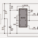
Parts List
R1 = 10 ohm
L1 = 9-0-9 turns, that is 18 turns with a center tap using a 30 SWG super enameled copper wire.
L2 = 18 turns using 30 SWG super enameled copper wire.
T1 = 2N2222
D1----D4 = 1N4007
C1 = 100uF/25V
3V = 2 AAA 1.5V cells in series
The image above shows a straightforward wireless power transfer circuit consisting of the transmitter stage on the left and the receiver stage on the right side of the design.
Both the stages can be seen separated with a significant air gap for the intended shift of electricity.
How it Works
The power transmitter stage looks like an oscillator circuit made through a feedback network circuit across an NPN transistor and an inductor.
Yes that's right the transmitter indeed is an oscillator stage which works in a push-pull manner for inducing a pulsating high frequency current in the associated coil (L1).
The induced high frequency current develops a corresponding amount of electromagnetic waves around the coil.
Being at a high frequency this electromagnetic field is able to tear apart through the air gap around it and reach out to a distance that be permissible depending upon its current rating.
The receiver stage may be seen consisting of only a complementing inductor L2 quite similar to L1, which has the sole role of accepting the transmitted electromagnetic waves and converting it back to a potential difference or electricity albeit at a lower power level due to the involved transmission losses through the air.
The electromagnetic waves generated from L1 is radiated all around, and L2 being somewhere in the line is hit by these EM waves. When this happens, the electrons inside the L2 wires are forced to oscillate at the same rate as the EM waves, which finally results in an induced electricity across L2 too.
The electricity is rectified and filtered appropriately by the connected bridge rectifier and C1 constituting an equivalent DC output across the shown output terminals.
Actually, if we carefully see the working principle of wireless power transfer we find it's nothing new but our age old transformer technology that we ordinarily use in our power supplies, SMPS units etc.
The only difference being the absence of the core which we normally find in our regular power supply transformers. The core helps to maximize (concentrate) the power transfer process, and introduce minimum losses which in turn increases the efficiency to a great extent
Inductor Core Selection
The core also allows the use of relatively lower frequencies for the process, to be precise around 50 to 100 Hz for iron core transformers while within 100kHz for ferrite core transformers.
However in our proposed article regarding how wireless power transfer functions, since the two sections need to be entirely aloof from each other, the use of a core becomes out of question, and the system is compelled to work without the comfort of an assisting core.
Without a core it becomes essential that a relatively higher frequency and also higher current is employed so that the transfer is able to initiate, which may be directly dependent on the distance between the transmitting and the receiving stages.
Summarizing the Concept
To Summarize, from the above discussion we can assume that to implement an optimal power transfer through air, we need to have the following parameters included in the design:
A correctly matched coil ratio with respect to the intended voltage induction.
A high frequency in the order of 200kHz to 500kHz or higher for the transmitter coil.
And a high current for the transmitter coil, depending on how much distance the radiated electromagnetic waves is required to be transferred.
For more info regarding how wireless transfer works, please feel free to comment.


Comments
When Tesla transmitted wireless power, he used longitudinal EM radiation, which he likened to sound waves in the aether. At Colorado Springs, he lit a number of light bulbs at a receiver 26 miles away from the transmitter. He used spherical antennas which could only transmit longitudinal EM waves. This is shown on his patents for the wireless transmission of electricity.
okay, ive gotten a few ideas from there, now its just to figure out how to woork around the circuit design to finish the project…
Swagatam thanks, i have check through the article but it still didnt give a direct way in how to go about doing the calculation for the coils, im still reading through some more article to see i can figure it out..
that's right cinnamon, please go ahead…
yeah Swagatam thanks, ive got an idea from this article. now i just have to develop the spec for my other circuits and put it together the the coil….
You can apply the explained principles to this circuit
https://www.homemade-circuits.com/2017/01/high-current-wireless-battery-charger.html
yeah i checked that article also and still didnt get through with it as well…
Did you check the following article also?
https://www.homemade-circuits.com/2016/09/designing-induction-heater-circuit.html
you will need to optimize the resonanace of the tank circuit to get maximum power transfer delivered across the other side…
good day sir im trying to have a power transfer of about 60w, how huge would the coils be and how can i go about calculating the size that the coils need to be, really need and appreciate your help. can you please help me out?
Cinnamon, you may have to calculate all the parameters correctly in order to implement the mentioned design efficiently and get success, you can go through the following article for all the details, and also the subsequent article:
https://www.homemade-circuits.com/2016/09/designing-induction-heater-circuit.html
Sorry sir how to expand the energy transfer distance how man..??
Angga, increasing distance can drastically affect the efficiency of the system therefore it's not recommended
Hello Sir, can this circuit output 7.5v at 750mA? I need a power source for a propeller clock and this seems to be a very good circuit because I don't want to use brushes, or how can I design the circuit to get that voltage and current? best regards.
Hello alexis, yes that's possible but I am not sure how the response would be since the receiver coil would be rotating at a high speed and possibly causing some unusual effect on the induction process
gauge is not important, it's the number of turns and a matched supply voltage which ensure a proper functioning of the circuit…gauge can be anything
How many gauge of copper wire did I need for this project? I have tried to work with 22 gauge of copper wire, but it didn't work. So please reply fast and tell me the other basic knowledge.
Sir, we made the circuit using ferrite core and specifications mentioned in the above circuit daigram but when we switch on the battery the transistor becomes very hot and it seems the whole voltage drop is across the transistor. ….. it would be helpful.if you could provide any solutions
Anu, please do it as per this article
https://www.homemade-circuits.com/2016/09/designing-induction-heater-circuit.html
Sir you mentioned that both the inductors should have 18 turns. What should be the size (diameter or area of cross-section) of the cylindrical core on which we have to wind the coil?? What should be the value of inductance of both the inductors?? Please reply sir it would be a great help.
YN, you can try a ferrite ring, as shown below:
coil32.net/images/img/hlp/ferrite_torroid.jpg
If I want to transmit power over a distance of 20m wirelessly with a voltage of 220V. Please, what are the requirements in calculation and materials?
Thank you!
that's not feasible because it might not yield anything usable at the receiving end
when something is wireless it has to pass through air, for wireless power transfer high amount of current needs to be passed through air, which becomes extremely difficult due to the high resistance of air…therefore presently it looks impossible.
yes that may be possible but the coils will need to be significantly huge, may be in the range of a couple of square meters
No that cannot be possible, because the present wireless transmission tech requires the load to be very near to the transmitter
sir, I got 3.5v at the o/p ,but to use 7805 we required min 7v..!
so, what changes we do in the ckt so we get 7v at the o/p…?
You can try increasing the number of turns of the receiver circuit
I need a circuit diagram of transistor power energy transfer and mobile phone jammer
Hi Sir i have problem i try make Wireless Power Transfer.i don't kwon about wire 30 swg sir…sir i have a roller how mny cm or mm wire sir…im sorry sir b'coz x finish study but experience sir 27 years…SIR I like electronics make…TQ SIR
Hi Alpher, you can try any suitable thin enameled copper wire, thickness is not critical since current is low…
i need some transistor based mini project which must be different and good
Hii Sir ,
I want to make a circuit which convert 5v 5amps into 5v 1amps . Sir i want your help please help me .
Regard
check datasheet to correct yourself.
78XX are all internally protected from overheating, output short-circuit, overload, and input voltages upto 35V
As per my knowledge, 78xx series regulators have only temperature protection circuit… Not any over voltage or current / short circuit protection.
Hi Ravi, a 7805 will never burn due to overload or a short circuit, as it's internally protected for all these issues, but it will need to be adequately heatsinked for getting optimal an response from it
Swagatam, if 7805 is used, it would only drop the output voltage. If the connected circuit draws current over 1.5 amp, 7805 itself would burn. For reducing the current rating, a ferrite core transformer with similar primary to secondary turn ratio, but having thin secondary winding wire would solve the purpose. I hope you could suggest proper calculations & other components required.
Hi Mayank
use a 7805 IC…however the output V might drop a bit.
Sir how can I transfer 12v.
as explained here:
https://www.homemade-circuits.com/2015/09/wireless-cellphone-charger-circuit.html
Sir,how much distance I can transfer this energy
not more than 1 inch…