A wireless mobile phone battery charger is a device that charges a compatible cellphone or mobile phone placed close to it, through high frequency wireless current transfer, without any physical contact.
In this post I have explained how to build a wireless cellphone battery charger circuit for facilitating a cordless cellphone charging without employing a conventional charger.
The Objective
Here the cellphone is required to be installed with a receiver circuit module internally and connected to the charging socket pins, for implementing the wireless charging process.Once this is done, the cellphone simply needs to be kept over the wireless charger unit for initiating the proposed wireless charging.
In one of our earlier posts I have explained a similar concept which explained the charging of a Li-ion battery through a wireless mode, here too we employ a similar technique but try to implement the same without removing the battery from the cellphone.
Also, in our previous post I will comprehensively explained the basics of wireless charging, we'll take the help of the instructions presented there and try to design the proposed wireless cellphone charger circuit.
We'll begin with the power transmitter circuit which is the base unit and is supposed to be attached with the mains supply and for radiating the power to the cellphone module.
The Transmitter (Tx) Coil Specifications:
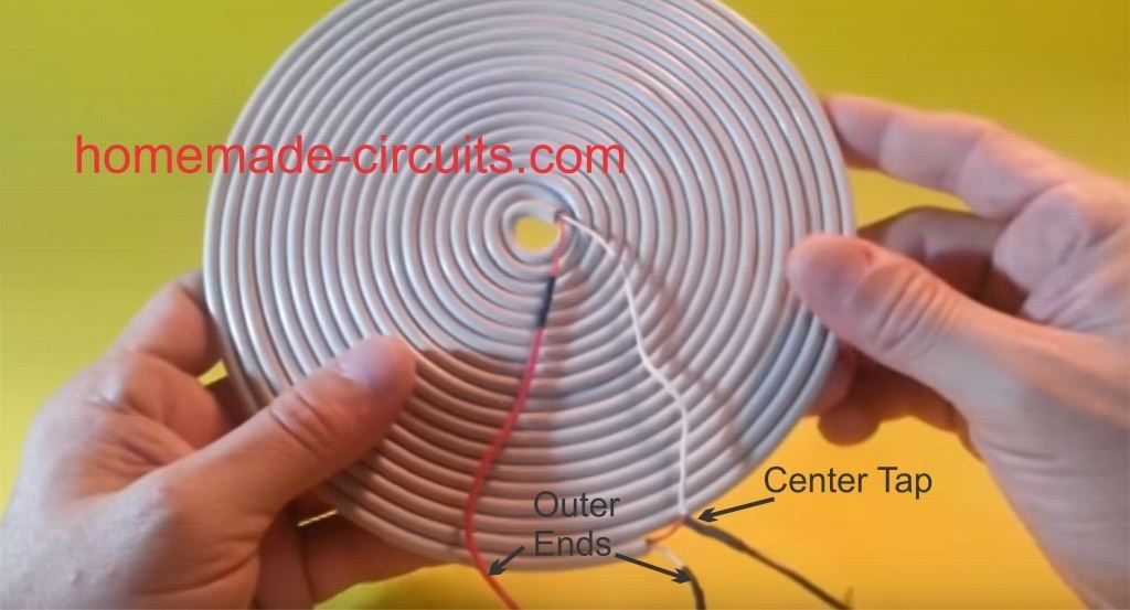
The transmitter circuit for this wireless cellphone battery charger is the crucial stage and must be built accurately, and it must be structured as per the popular Tesla's pancake coil arrangement as shown below:
Making a PCB version of the above Pancake coil.
Inspired from the above theory, the smaller layout of the same coil can be etched over a PCB as shown in the following diagram, and wired as indicated:
Dimensions: 10 inches by 10 inches, bigger size might enable faster charging and better current output
The figure above shows the power emitter or radiator design, also recall the circuit diagram from our previous post, the above design utilizes exactly the same circuit layout, although here we do it through a PCB by etching the winding layout over it.
A careful observation shows that the above layout has a pair of parallel coiled copper tracks running spirally, and forming the two halves of the transmitter coil, wherein the center tap is acquired with the aid of the linked red jumper wire across the ends of the coils.
The layout allows the design to be compact and effective for the required operations.
The track layout could be in the form of a square, or oval on one side and squarish on the other in order to make the unit even sleeker.
Rest of the portion is quite straightforward and is as per our earlier diagram, where the transistor is 2N2222 included for inducing the required high frequency oscillations and propagation.
The circuit is operated from a 12V/1.5 amp source, and the number of turns (coils) may selected approximately in accordance with the supply voltage value, that is around 15 to 20 turns for each halves of the transmitter coil. Higher turns will result in lower current and boosted voltage radiations and vice versa
When switched ON, the circuit may be expected to generate a strong magnetic flux around the coiled tracked, equivalent to the input power.
Now the radiated power needs to be absorbed using an identical circuit for executing the wireless power transfer and the intended cell phone charging.
For this we need a power collector or receiver circuit for collecting the radiated power, this may be devised as explained in the following section:
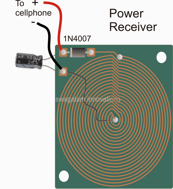
Dimension: 3 inches by 3 inches or as per the accommodation space available inside your cellphone
As may be witnessed in the above receiver design, an identical layout of the coil may seen, except that here the two concentric spirals are connected in parallel to add current in contrast to the transmitter layout which incorporated a series connection owing to the center tap restriction for the design.
The design is supposed to be small enough to fit inside a standard cellphone, just below the hind cover, and the output which is terminated through a diode may be connected either with the battery directly or across the charging socket pins (internally).
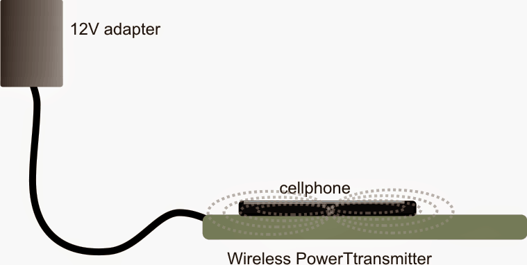
Once the above mobile battery charger circuits are built, the transmitter circuit may be connected with the indicated DC input, and the receiver module placed right over the transmitter board, at the center.
An LED with a 1k resistor could be included at the output of the receiver circuit in order to get a instant indication of the wireless power conduction process.
After the operation is confirmed, the output from the receiver may be connected to the socket of the cell phone for checking the response of the wireless charging effect.
However before this you may want to confirm the output to the cellphone from the wireless receiver module...it should be around 5 to 6V, if it's more, the black wire could be simply shifted and soldered a few coils towards the top until the right voltage is achieved.
Once all the confirmation are complete the module could be accommodated inside a cellphone and the connections done appropriately.
Finally, hopefully if everything is done correctly the assembly might allow you to keep the cellphone directly over the transmitter set up and enable the proposed wireless cellphone charging to happen successfully.
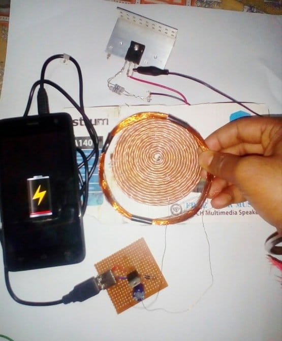
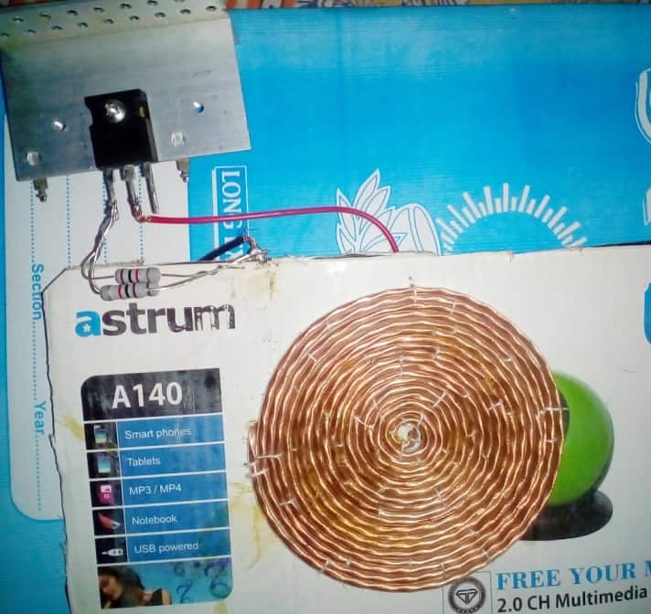
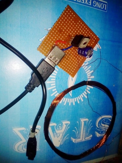
Making a Practical Prototype
The above wireless power transfer concept was successfully tried and tested with some modifications, by Mr. Narottam Gupta who is an an avid follower of this blog.
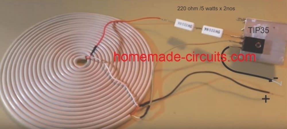
The modified wireless cellphone charger circuit diagram and the prototype images can be witnessed below:
Detailed Working Description
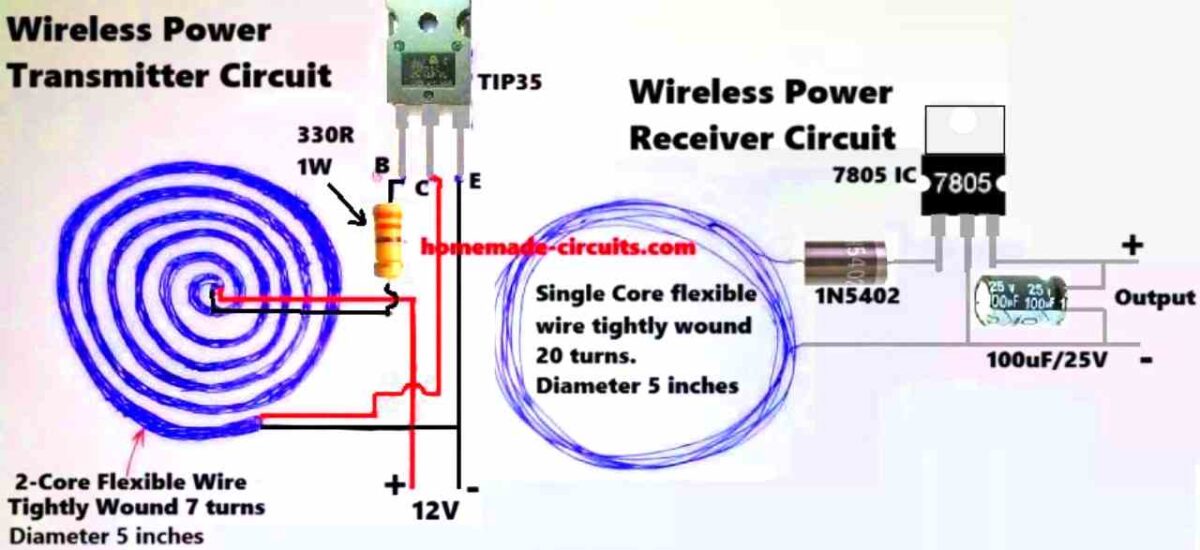
We have got the transmitter coil which is designed as a center-tapped transformer. What this means is that there is a center tap that connects to the positive supply voltage which is at +12V. The two ends of the coil are then alternately switched to ground through the TIP35 transistor while we are running the circuit.
Transistor Switching
Now here is where it gets interesting with the TIP35. We have set it up as a self-oscillating transistor. This whole setup relies on feedback from one side of the coil back to the base of the transistor to keep those oscillations going strong. To get things started we have got a 330 Ω resistor connected to the base of the TIP35. This little guy provides the initial biasing needed to turn the transistor on just for a moment.
Induced Feedback
When current starts flowing through one half of our coil it creates a magnetic field in the transformer core. This magnetic field then induces a voltage in the other half of the coil which gives us that all-important feedback signal back to the TIP35's base. What is cool is that this feedback signal alternates in polarity which makes the transistor switch on and off.
Oscillation Formation
Thanks to this alternating feedback polarity our transistor keeps turning on and off repeatedly. This action creates oscillations in the coil and these oscillations generate an alternating magnetic field in our transmitter coil. This is what we use to wirelessly transfer power.
Role of the Center Tap
Now let us talk about that center tap again. It splits our transformer into two halves allowing the transistor to alternate current flow between them. This back-and-forth current flow is what actually generates those oscillations we have been talking about.
Main Features of the Oscillation
Finally let us touch on some key features of our oscillation. The frequency at which these oscillations occur is mainly determined by two things: the inductance of our coil and any stray capacitance present in the circuit. Since we are not using an explicit capacitor here we end up relying on:
The stray capacitance that exists between the coil windings.
The parasitic capacitance from the TIP35 transistor itself.
Prototype Description
We built this coil out of a flexible 2-core wire that is wound around 7 times and has a diameter of around 5 inches. This coil acts as the inductive element (L) in our LC circuit and its primary function is to generate an oscillating magnetic field at a specified frequency.
Next we have a 330-ohm resistor which restricts the base current flowing to the TIP35 transistor and also provides the necessary biasing conditions for it to function effectively.
The TIP35 is an NPN power transistor that can function as both a high-current switch and an oscillator. It is critical since it boosts the current required to drive that coil adequately.
The power supply outputs 12 volts of direct current which supplies the required input voltage to keep things working properly.
This is how the whole thing works. The circuit is a self-oscillating feedback loop. When we turn it on, the current flows into the TIP35's base via the 330 ohm resistor. A resonant LC circuit is made up of the coil, its inductance, and some parasitic or stray capacitance. The oscillation frequency is determined by the following formula:
f = 1 / (2 * π * √(L * C))where L is the inductance of the coil and C is that stray capacitance.
This resonant LC circuit produces oscillations at its natural frequency. The magnetic field formed by the current running through the coil produces an oscillating voltage which is supplied back to the TIP35's base to keep the oscillations continuing strong.
The TIP35 turns on and off fast sending high-frequency current through the coil. This action creates a strong oscillating magnetic field around the coil.
This pulsing magnetic field induces a voltage in a surrounding receiver coil using Faraday's law of electromagnetic induction. Essentially we are wirelessly transmitting energy from the transmitter coil to the receiver coil!
So why is this circuit oscillating? It all boils down to how the LC tank circuit (which consists of our transmitter coil and capacitance) interacts with the TIP35 transistor. The transistor amplifies the oscillations and then through our feedback loop the generated voltage in the coil reinforces the transistor's switching activity keeping those oscillations going.
The frequency at which our transmitter runs is determined by both the coil's inductance (L) and stray capacitance. If we know these numbers we can use our prior calculation to get the frequency.
Note:
It's worth noting that this circuit doesn't employ a dedicated capacitor, instead relying on stray capacitance from the coil and the wires. This can make our frequency more varied.
The TIP35 is designed to handle high power ensuring that there is enough current to create the required strong magnetic field.
If we wish to fine-tune the circuit we may do so by varying the inductance of the coil—by changing the number of turns or the spacing between them. This could help us create resonance with the receiver coil, resulting in optimal efficiency.
Formulas and Calculations
Transmitter Coil Design
Inductance (L) of the Coil:
L = (N2 * mu0 * A) / l- Where:
- N = 7 (number of turns in the transmitter coil)
- mu0 = 4 * π * 10-7 H/m (permeability of free space)
- A = π * r2 (cross-sectional area of the coil, r is the radius in meters)
- l = length of the coil (assume tightly wound with negligible height)
Diameter of Coil: 5 inches = 0.127 m
Radius: r = 0.127 / 2 = 0.0635 m
Cross-sectional area:
A = π * (0.0635)2 = 0.01267 m2Receiver Coil Design
For the receiver coil:
N = 20 (number of turns in the receiver coil)
Use the same formula for L as above with N = 20.
Resonant Frequency (f):
f = 1 / (2 * π * √(L * C))- Where:
- L is the inductance (calculated for both coils)
- C is the capacitance in the transmitter circuit (typically provided by a tuning capacitor or parasitic capacitance)
Power Output:
The receiver circuit includes a rectifier (1N5402) and a voltage regulator (7805) to step down and stabilize the output.
Power output:
P = V * IIf we Assume the output voltage is 5V (regulated by 7805) and the current depends on the load.
Efficiency of Power Transfer:
Efficiency (eta):
eta = (Pout / Pin) * 100%- Where:
- Pin is the power supplied to the transmitter circuit
- Pout is the power delivered to the load via the receiver circuit
Power Dissipation in the Resistor:
The resistor in the transmitter circuit is 330 ohms 1W.
Power dissipation:
PR = I2 * ROr:
PR = V2 / RAssuming input voltage V = 12 V:
PR = (122) / 330 = 0.436 WThe resistor rating of 1W is safe for this application.
Receiver Side Voltage:
Diode drop for 1N5402:
Each diode drop is approximately 0.7V (forward voltage).
Output after rectification:
Vrectified = VAC - 2 * VdiodeVrectified = VAC - 1.4VAfter 7805:
Vout = 5VTested Prototype Images


Questions & Answers
Hi ! I’m truly delighted by your innovative approach. However, I have one confusion. If I am not wrong, the mobile wireless charger adapters used have an output of only 5 volts but your circuit needs a 12v adapter suppky for transmitter side. Please help me rsolve/remove my confusion.
Hi, thanks, and Glad you liked my circuit ideas.
12V will be required for wireless input supply because wireless chargers require high voltage and high current supplies, otherwise it cannot work optimally.
The supply from the wireless receiver can be regulated to 5V for charging the phone…
All this is very interesting. Do you have any truly beginner friendly introductory material to help understand various components, their functional relationships and outcomes they cause? Thanks so much
Thank you for your interest in this article, I will try to update the article soon with explanation regarding the working of each component in the design…
Sir I have to discuss about 24 volt induction.
Hi Swagatam, I hope you are well.
I wanted to ask you if it seems possible to make a 42V – 2A wireless charger for an electric scooter with a designer circuit.
Thanks a lot in advance
Hi Juan,
I may be possible to build it if you are able to optimize the resonance frequency of the circuit correctly.
If we can calculate the frequency and the resonance components of the circuit correctly then it will be successful.
Hi Sir. I just want to ask how do you trigger the coil? I didn’t understand the working principle. Why didn’t you switch the Tx coil?
Hi Halil, the coil is triggered and oscillated by the transistor through a feedback mechanism.
I am a student, what you did is almost the same as what I did. My project is about a table that charges a laptop wirelessly.
Can you do a simulation for my project like what you did on this page? Because I don’t know how to do a simulation.
Sorry, I am also not good with simulations, so it might not be possible for me, by the way I cannot see any simulation done in the above article…
Hello.I want to design the pcb file of this circuit..but I need calculations for board thickness.track thickness.distance between tracks and number of coils..please guide me Wireless Cellphone Battery Charger Circuit
Hi, Sorry, I do not have the exact dimensions of the board, it was designed as per my imaginations and assumptions. You will have to consult a professional PCB designer for getting the exact size and thickness. Track thickness can be 1.5 mm.
Sir on the top there you said in the transmitter coil(Rx) more turns result in higher voltage lower current while less turns result in lower voltage higher current right please correct me if I’m mistaken. It may be the reason why my power bank was unable to charge my phone maybe doe to higher voltage and lower current
Hi Sadiq, yes that’s correct. However the transmitter turns must be properly calculated with regards to the input supply voltage and must not be too less. The same is true for the secondary winding.
I meant the transmitter coil (Tx).
Pls sir what’s the diameter of the reciever coil
You can use any thin enameled copper wire, for example which are used in 1 amp transformer secondary side. Can be 0.3 mm diameter
Ok sir.so how about the coil inductance calculation and the matching resonance frequency calculation
Resonance has not been applied in the above circuits.
Pls sir why’s the transmitter coil thicker than the reciever coil and how can I calculate the coil inductance for both the transmitter and receiver and also the matching resonance frequency
Hi Melvis, it is because the receiver coil has more number of turns than the transmitter so that it can absorb maximum wireless transmission from the transmitter coil. Transmitter needs less number of turns in order to match with the transmitter frequency and to enable high current output. However, the receiver coil can also have the same number of turns as the transmitter and the same wire thickness.
What other type of capacitor can i use instead of an electrolytic capacitor
Any type of capacitor can be used but the value must be higher than 100uF
Sir Tp35C is heatup, and there is no voltage in Rx.
You will need a heatsink for it, but the circuit must oscillate first, there are many good videos on Youtube, please watch them…
Sir My circuit is running , but with 12V dc adapter, due to Transistor TIP35C. When I put 2N2222 transistor for 5V dc adapter then 2N2222 transistor is melting , So what is the method in which i can operate on 5V dc Adapter.
How can you say your circuit is running? Circuit will be running if the circuit oscillating with some frequency. If your connections are correct and your coils are correctly wound then you will get the results instantly. Check your two core wire connections with the transistor, turns must be tightly stuck with each there.
Sir, as shown in the images, the turns of Tx and Rx are same but thickness and thinness of Tx and Rx is different. But you tell me that Rx turns greater than Tx.
Sam, there are fixed rules for making this project, everything is linearly proportionate. Lower Rx turns will give lower voltage output and vice versa.
Sir, In your computerized Image the turns of Tx of 2 Core wire are 10…But at the below a real image in which the number of tutns are 20 of white 2 core wire???
20 is better, higher the number turns the better will be the results
Sir, as shown in the images, the turns of Tx and Rx are but thickness and thinness of Tx and Rx different. But you tell me that Rx turns greater than Tx.
If i used same 2 core Speaker wire for Rx coil Is it right???
Can I make 2.5 inches of diameter of Rx ?… Where Diameter of My Tx coil is 5 inches.
In 2 core Speaker wire of Tx of the wire guege number is 28 Can i use 18 number for receiver coil.
please do it as shown in the images, Tx wire should be thicker, and Rx wire should be slightly thinner. Rx coil must have higher number of turns than the Tx.
Sir what type of medium will used between coils and i have speaker 2 core wire is it right
Sir what type of medium will used between coils and i have speaker 2 core wire is it right
Sam, The medium is air core….yes two core speaker wire will do
Sir thanks to reply very soon,
Sir can i use sigle copper wire for receiver coil. How many turns give into receiver coil according to single copper wire , because 2 core speaker wire not adjust at my backside of phone , i give 20 turns of 2 core speaker wire in Tx.