In this article I have explained a permanent indicator of the windshield washer fluid level. Knowing that electronics do not mix well with liquids, instead of using a float gauge system, we have devised a completely different operating principle for you.
The operation of our circuit is based on timing the duration of the motor's activation that drives the washer pump. Once the reservoir is filled, the module will need to be switched ON. Its display will then show the letter "P" for "Full". Subsequently, as the washer fluid is used, a countdown timer will be incremented accordingly to display the digits 9, 8... down to the value 0, which corresponds to an empty reservoir.
Of course, this windshield fluid indicator circuit will need to be constantly maintained under the 12-volt potential of the car, even when it is parked, for obvious reasons of maintaining the counting positions in memory. However, this will not discharge the battery since this idle situation, during which the display is turned off, will result in an almost zero power consumption of around 2.5 mA. Under these conditions, it would take 20,000 hours to discharge a 50 AH battery.
Power and Connections
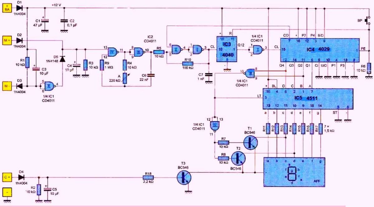
As indicated above, the setup will remain connected permanently between the positive polarity of the battery (+ BA) and the ground (-) of the vehicle, upstream of the power supply established at the time of key or card contact. Diode D1 acts as a guide. Capacitor C1 performs the necessary filtering while C2 isolates the power supply setup (Figure 1).
In general, the operation of the washer pump motor device is characterized by the appearance of a 12-volt potential on its positive terminal (M+). This potential, conveyed by D2, results in a "high state" on the positive armature of capacitor C4. There may be vehicle models in which the positive terminal of the pump motor is constantly subjected to positive potential and the starting is realized by connecting the negative terminal to ground.
In this case, it is sufficient to connect this terminal to the input (M-) of the setup. Thanks to the inversion provided by NAND gate II of 1C1, the result on the positive armature of C4 will remain the same, namely a "high state" when the pump is requested.
Finally, the input (C+) must be connected to a power point on which the positive polarity appears once the contact is established. On certain types of vehicles, this point can be, for example, the cigarette lighter. Through D4, a "high state" is then available on the positive armature of C5 and transistor T3 saturates. We will see later that this corresponds to the activation of the display.
In the situation where the display is turned off, the consumption is around 2.5 mA, as we have already indicated. When the display turns on, this consumption increases to about 50 mA.
Timebase for timing
The timing base for the chronometer is formed by the NAND gates III and IV of IC2, which create an astable oscillator controlled by input (13). As long as input (13) is in a low state, the oscillator is blocked and its output is also in a low state.
However, when the motor of the windshield washer device is running, input (13) is in a high state and the oscillator generates a sequence of square waves on its output, the period of which depends essentially on the angular position of the adjustable A. We will see later how the adjustable A can be set. In the median position, the period of the generated square waves is approximately 6 milliseconds.
The Schmitt trigger, consisting of NAND gates I and II of IC2 and their peripheral resistors R5 and R10, gives these rising and falling edge signals a more vertical shape, which makes them suitable for transmission to the "Clock" input of the counter IC3. This counter is a CD4040 and is composed of twelve binary counters connected in cascade. Therefore, it performs a division by 2^12, which is 4096.
For a median position of the adjustable A, the period of the square wave available on the Q12 output of IC3 is thus 6 ms x 4096, which is approximately 25 seconds. The NAND gate I of IC1 inverts these square waves, so that after this period of 25 seconds, the output of this gate presents a rising edge.
Countdown
The IC4 reference integrated circuit is a presettable binary/BCD up/down counter: the CD 4029. In the present use, it operates in countdown mode at the pace of the descending edges of the signals present on its "Clock" input. This is why its "Up/Down" input is connected to a low state 0.
Given that the "Binary/Decade" input is in a high state 1, the counting system implemented is binary, that is, it is capable of counting down from the position 15 (1111 in binary notation on the Q1 to Q4 outputs) to the value zero.
When the "Preset Enable" input is set to a high state, the counter is preset to the binary value imposed by the logic levels applied to inputs P1 to P4.
In the present case, this value corresponds to the binary notation 1010 (read from P4 to P1), which is equivalent to the decimal value 10. Thus, the counter is positioned on this maximum value when the reset push button BP is pressed.
Note that at the same time, counter IC3 is also reset to zero.
Subsequently, as the operating directions of the washer motor are integrated, counter IC4 ensures countdown by successively positioning itself on values 9, 8... until it reaches the value 0. In this case, and since the counter operates in countdown mode, the "Carry Out" output presents a low state 0.
Note that this output presents a high state for all other counter positions.
Thus, when the zero position is reached, input (6) of Schmitt trigger NAND I and II of IC2 is set to a low state. The counting pulses from the astable oscillator are no longer transmitted, the counter is neutralized, and remains locked on the zero position, even if the washer pump drive motor continues to be activated.
Display
The logical levels from counter IC4 and available on outputs Q1 to Q4 are routed to the decoding inputs A, B, C, and D of the decoder 105, which is a CD 4511. This is a BCD/7-segment decoder with a common cathode. Except for the particular position 10 of IC4, which I will elucidate later, this decoder provides the "high" and "low" states required to configure the display of numbers from 0 to 9 on its outputs labeled (a) to (g). Resistors R11 to R17 limit the current in the segments.
When transistor T3 is saturated, the display is normal, given the possibility of returning the current from the common cathode of the display to the negative supply. The display turns off if this transistor is blocked, meaning that the key contact is not established.
Fuel Tank Display
While initializing the windshield washer fluid indicator circuit after filling the fuel tank, we saw that the counter IC4 was positioned at the decimal value of 10. This does not correspond to any decoding possibility from the decoder IC5. The NAND III gate of IC1 detects this particular position of IC4. This is indeed a position for which the two inputs of the NAND gate are simultaneously subjected to a "high" state. The output then presents a "low" state.
Since the "Lamp Test" input of IC5 is also subjected to this "low" state, all outputs from (a) to (g) switch to the "high" state. If no special precaution were taken, the display would show the configuration corresponding to 8. But the output of the NAND IV gate of 1C1 switches to the "high" state. This results in the saturation of the NPN/T1 and T2 transistors. Consequently, the (c) and (d) inputs of the display are forced to zero and the two corresponding segments turn off.
As a result, the display shows the configuration "P", indicating a full fuel tank.
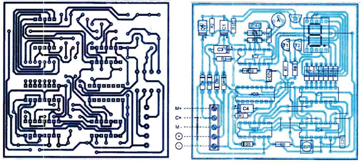
How to Implement
The following figure shows the printed circuit board of the circuit which requires few comments regarding its realization. The placement of components is indicated in adjoining figure below. As always, care must be taken to ensure the correct orientation of polarized components. Note that diode D3 has an orientation opposite to that of its neighboring diodes.
Once the assembly is ready to function, it only remains to adjust the timing base. This involves determining the operating time of the pump needed to completely empty the tank. The simplest method is to fill the tank completely, possibly with water that has been well filtered beforehand, and to time the duration of operation needed to empty it.
For example, if this time is 250 seconds, one can adjust the oscillator's timing base to obtain a period of 250/10, or 25 seconds, on output Q12 (pin no. 1 of IC3), or, to obtain a faster response, a period of 6.25 seconds, or 250/40, on output Q10 (pin no. 14). The period increases if the adjuster's cursor is turned clockwise, and vice versa.
Note: If there is not enough space available to install the module on the dashboard, it is still possible to install only the display. In this case, it is necessary to connect the display to the module via a cable made up of eight conductors.


Comments
There has not been a cigarette lighter on American
cars in 25 years, the last cars with a positive ground
was in 1954.