The simple DC shunt motor controller circuit presented in the following article uses a variac. This design facilitates an instant stopping of the motor at any stage with a flick of a switch, along with reversing the motor direction. It also provides speed control for the motor with a high level of accuracy.
Overview
TRIAC and SCR half-wave motor controller for small series motors are quite popular and cheap and they are being already a part of portable power tools and compact appliances.
Having said that, electronic speed controls for bigger d.c. motors of 1/4 and 1/3 HP are actually more complicated.
Large DC shunt Motors in this horsepower range are, additionally, the favorites of the motor industry, operating from loft fans to drill presses; although basically all these types of motors are a.c. induction motors having just one speed or, maybe, a couple of variable speeds.
While a 1/3-horsepower, 1750 RPmin, 117 volt shunt-wound d.c. motor can be expensive, it might be worth the price and you can find a few on the surplus market place.
With an appropriate speed control, these d.c. motors can be a wonderful thing to see, operating a drill press or a lathe machine.
How a DC Shunt Motor Works
DC shunt motor runs pretty much with a constant speed, irrespective of the load. These motors are typically used in industrial applications and is generally preferred where starting up situations aren't often severe.
Shunt-wound motor speed could be controlled by a couple of methods: first, by placing a resistance in series with the motor armature, that might consequently slow down its speed: and second, by placing a resistance in series with the field wiring where the speed might show a change with change in the load. In the latter case, the speeds will remain virtually stable for a given setting, and load on the controller. This latter is considered the most commonly used for adjustable-speed facility, such as in machine tools.
The shunt motor is perhaps the most widespread dc motor found in industry these days. The shunt motor basically consists of the armature, marked as A1 and A2, and the field wires, marked F1 and F2.
The winding in the shunt field consist of several turns of thin wire, contributing to low shunt field current and reasonable armature current. Shunt DC motor allows starting up torque which may vary with the load specs, which can be countered through precise controlling of the shunt field voltage.
Importance of Field Coil
In case the field coil is cut-off in a shunt motor, it may speed up somewhat until the back EMF goes up to a level just enough to turn off the torque generating current. Put simply, the shunt motor will never damage on its own when it loses its field, but the torque power required to do the job will be simply removed, causing the motor to lose its main capability for which it had been designed.
Several of the typical applications of the DC shunt motor are machine shop lathes, and industry process lines which require crucial control of speed and torque on the motor.
Main Features
The main features of the circuit are, you are able to switch the speed knob for the speed control, along with a dynamic braking feature, that enables you to halt the heavy motor almost instantly; no waiting around as the motor coasts along.
The variac based DC shunt motor speed-control circuit as shown below, functions nicely on one of these 1/3- horsepower d.c. motor, it isn't crucial as to what type of motor it is controlling, so long as its rated voltage matches the input supply, is shunt-wound, and works with a maximum of around 3 amperes at 100 % load.
Using a Variac Autotransformer
The shown circuit is incorporates a device which many engineers may consider quite crude and old fashioned, yes it is the variable autotransformer.
Among the many useful features, a variac will enable a powerful braking to your high power motor, it can work without depending on feedback loops: which ensures minimum instability or no incompatibility with different forms of motors or disparities in mechanical load.
How it Works
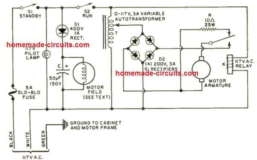
In the variac based DC shunt speed-control circuit of Fig. 1, half-wave rectifier D1 provides the shunt field for the d.c. motor. Filter capacitor C provides the necessary amount of voltage and removes any bit of instability in the operations that could be existing with an unfiltered field supply. Variable autotransformer T regulates the armature voltage thus the speed of the motor.
The output from the variac is given to a standard bridge, rectifier D2. The rectifier output is given to the motor armature by means of the N/O contacts of a switched ON 117-volt a.c. relay K.
Any time the motor needs to be halted, the "Run" switch S2 is opened, which changes over its normally closed contacts and links up the dynamic braking resistor R across the armature.
During the period the motor coasts, it functions like a d.c. generator. The power generated due to is is dissipated in the resistor R, causing the motor to get loaded adequately, and this forces the motor to stop abruptly.
Considering that the motor field coil needs to be energized for implementing the braking action , an independent switch S1 is included for the field supply.
As a result, while the system is operational, S1 is kept switched ON, enabling the pilot light as a warning lamp. The field energy necessary for a regular 1/3- horsepower shunt motor is just around 35 watts, because the field resistance normally works with approximately 400 ohms.
Motor Specifications
Field current can be close to 350 mA. The rated full-load current of a 1/3-hp motor is close to 3 amperes d.c. or around 50 % of the line current consumed by a comparable a.c. induction motor.
The shunt d.c. motor includes a power factor of 100% and is particularly more efficient. Each of the parts operate without heating, except for braking resistor R. In the event the motor operates a load with a huge flywheel effect and is stopped repeatedly at increased speeds, the resistor will need to convert a great deal of kinetic energy into heat. With low-inertia loads such as a drill press, the resistors may not face any heating issue.
The contacts of relay K must be rated with no less than 10 amperes. Braking current is usually excessive, although appears for a short period of time; initial surges tend to be substantial since the d.c. resistance of the armature is normally just one or two ohms. The working current of the motor is, not surprisingly, limited by the amount of back e.m.f it generates.
Construction and Safety Tips
The DC shunt motor controller circuit demonstrated above could be constructed in a 6" x 6" x 6" metal power box.
Considering that the entire circuit is hot to ground at power-line voltage, mindful insulation and grounding are extremely vital for basic safety. The power cable must be of the 3-wire earthing type.
The green ground wire must be coupled to the metallic box and after that taken via to the framework of the motor. Please do not neglect or ignore using the fuse.
SCR Control vs Variac Control
Variable autotransformers or variacs are incredibly tough and long lasting. The output of these devices is low impedance therefore, the armature voltage provides excellent regulation towards variations in load current.
An SCR switching-mode circuit, with the smaller conduction angles, is naturally a rather high -impedance source and thus features inferior regulation.
Motor controllers using SCR's, consequently, include feedback loops specially designed into them, which makes the phase of the firing pulses based mostly on the back- e.m.f. of the motor and also on the control pot adjustments.
A well-designed full-wave SCR control is extremely good indeed, however it is actually complex with their design. In the 1/3 horsepower range, the variable autotransformer circuit is straightforward, efficient, and easier to assemble by the user.
In situations where the mechanical load on the motor has reduced inertia, it is occasionally sensible to leave out "Run" switch, S2, and control all from "Standby" switch S1.
The active braking may continue to do the job to some extent because of the surplus magnetic flux within the motor field winding.
Wherever this can be achievable, it offers the benefit of no "standby" dependability; everything is switched off right up until main switch S1 is toggled ON.
If the motor needs to be rotated in reverse, just configure a d.p.d.t. switch, attached criss-cross for the operations, across the armature supply and the armature.


Comments
Can someone help me with the 48v dc 3000w speed controller design diagram for a shunt motor please
Hi am trying to re build a DC shunt motor circuit that has been damaged. The circuit is for an old potters wheel that the speed is controled via a foot peddle attached to a variac. Im finding your circuit diagram very helpfull however I have some questions.
The output from the variac to the armature has no smoothing capacitor after the bridge rectifier, does it not need a capacitor?
Also in your diagram the field windigs on the positive side are powerd through a half wave rectifer and a capacitor, and the negative side conectid to neutral, AC. Am i interpretating this correctly.
I am a electrician and have limited knowlage of electronics also live in the UK so AC voltage is at 230V.
Thanks.
Hi, the filter capacitor is not crucial since the motor can probably work with an unfiltered DC. Yes, the field coil is connected to a half wave AC supply through the diode D1. The capacitor across the field coil is for suppressing noise
In the case of a blower motor of 250W, 1.6A, 3000RPM with brushes would the speed of the blower be increased with the increase of armature voltage using the presented speed controller. I may need a little more air from the blower with increase RPM.