In this post I have explained a universal ESC circuit or an electronic speed controller circuit which can be universally applied for controlling any type 3 phase BLDC or even an alternator motor.
What is an ESC
An ESC or electronic speed controller is an electronic circuit which is normally used for operating and controlling a BLDC 3-phase motor.
BLDC motor stands for brushless DC motor which clearly states that such motors are void of brushes, quite opposite to the brushed type of motors which rely on brushes for commutation.
Due to the absence of brushes BLDC motors are able to operate with maximum efficiency since the absence of brushes relieves it from frictions and other related inefficiency.
However BLDC motors have one major downside, these cannot be operated through a single supply like the other brushed motors, instead a BLDC motor requires a 3-phase driver for operating them.
Despite of this technical complexity, BLDC motors become highly preferable compared to their brushed counterpart, because BLDC motors are extremely efficient in terms power consumption and virtually no wear and tear issues.
This is why BLDC motors are today used in electric vehicles, windmills, airplanes, quad copters, and most motor related equipment.
As discussed above operating a BLDC motor looks quite complex, and if you try to look for a driver or an electronic speed controller circuit for BLDC motors you would probably come across circuits which are too complex using MCUs, or employ hard to find components.
In this post I have explained how to make a simple and effective ESC circuit which may be universally applied to operate most BLDC motors through some minor modifications.
Once you learn the details of the circuit, you could use it to build electric vehicles, quad copters, robots, automatic gates, vacuum cleaner and any motor operated product with maximum efficiency.
Three Phase Generator Circuits
Since a BLDC motor requires a 3 phase signal, the first thing that needs to be designed is a 3-phase generator circuit.
The following circuits show how this can be made using a handful of operating parts.The first one uses opamps while the second one makes use of just a few BJTs.
Simple 3 phase Generators
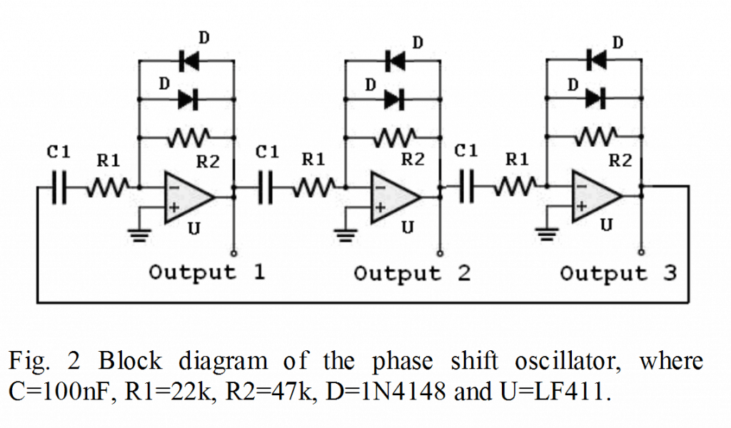
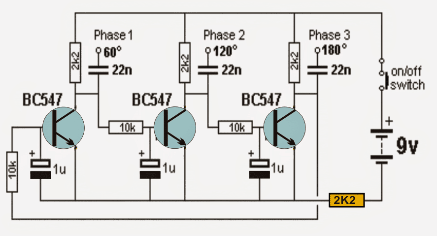
The 3-phase signal output needs to be integrated with a 3-phase mosfet driver circuit for enabling the motor operation.
Therefore the second important element is the 3 phase alternator driver circuit, which is supposed to respond to the above 3 phase generator circuit for operating the connected BLDC motor.
For a 3 phase driver, you could employ any standard 3-phase driver IC, such as a A4915, 6EDL04I06NT, or our old:
- IRS2330(D) (2.5µs deadtime)
- IRS2332(D) (0.8µs deadtime)
In our universal ESC circuit we will use the IRS2330 and see how this can be configured for the intended electronic speed control and implemented for most BLDC motors. The following image shows the entire circuit of the proposed ESC design.
The ESC Schematic
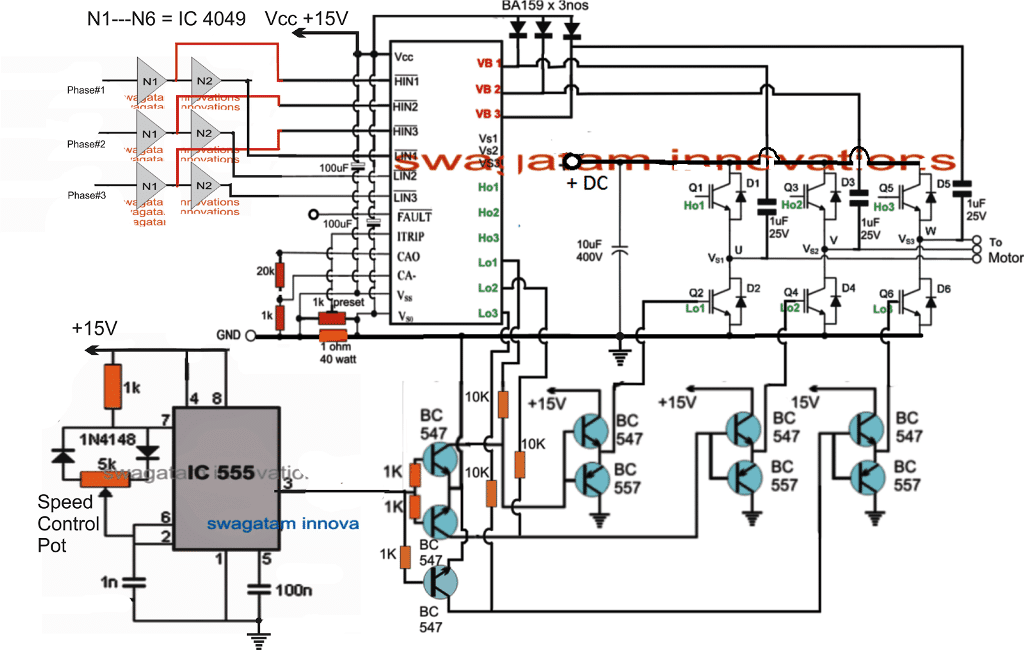
The presented ESC alternator driver circuit looks pretty straightforward and does not seem to employ any complex stages.
The 3 phase signals acquired from the 3 phase generator circuits is applied to the inputs of the NOT gates shown at the top left of the above diagram.
These 3 phase signals are converted into the required HIN, and LIN inputs for the 3 phase MOSFET driver IC IRS2330.
The IC IRS2330 hence process these signals to operate the connected BLDC motor with the correct phase and torque via the associated driver mosfets or IGBTs.
We can also see an IC 555 based PWM stage. This stage is configured with the low side mosfets or IGBTs, for chopping their gate triggers into appropriate sections.
This gate chopping forces the devices to operate at a rate determined by these chopping PWM duty cycle rate. Wider duty cycles enables the motor to rotate faster and narrower duty cycle allows the motor to slow down proportionately.
The PWM rate is controlled through the IC 555 through the indicated PWM pot.
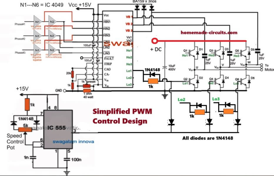
Simplifying the PWM Control of the IGBTs
The above universal ESC BLDC speed controller circuit can be further simplified by eliminating the complex BJTs stages at the low side IGBT PWM control section, as shown below:


Discussion & Solutions
is this for a sensor less motor?
both types can be used
Not sure my last question was posted. Thank you for your answer I really appreciate it. I have another, how can reversing be added to this example?
Thank you for the response. how about forward and reverse directions. How can this be accomplished?
forward reverse facility is not provided in the IC, however I think it can be implemented by reversing the 3-phase signal input's logic sequence.
Thank you. I was looking at that as an option.
I had same question on another post today. Will consider swapping two of the hall inputs but seems like hall inputs will track motor direction. May just need to get motor rolling using this approach then switch to hall sensors
OK, you can try that…
Thank you Mr Swagatam. I’d like to know the value of the 6 MOSFETs used for the bridge and also the value of the diodes. I need to construct an ESC for a project that I’m on. I’ve converted a car alternator to a hybrid bldc motor powered through an ESC for RC hobbies. Unfortunately the motor doesn’t have enough torque as I’d like it to be. I was wondering if this circuit will be powerful enough to run the motor under load.
Thank you, awaiting your response.
Thanks Mthokozisi, the mosfets can be as per the user’s choice, depending on how much power the output load may be rated at. You can use any suitable ones which may be on par with the rating of the motor. It is better to use IGBTs instead of mosfets for better efficiency.
This circuit can be upgraded for any motor, simply by upgrading the IGBTs accordingly.
Hi Swagatam, I’m trying to make a controller for 250W bldc motor. What should be the configuration for it? Can you please get in touch on email?
Hi Rishee, the configuration in the above article is the best configuration according to me, because it does not rely on any special ICs.
You can replace the full-bridge IC with any other variant, and use the other mentioned stages with it in the same format and achieve the required results.
You can feel free to discuss through comments, as this will help the other readers also to learn about your experience in the field.
Gooday. Thank you Sir again for your response, your work is simply priceless. For my project I have a sensorless motor(no Hall sensors), but I can’t find the chip for the sensorless esc https://www.homemade-circuits.com/2017/08/high-current-sensorless-bldc-motor.html
I need to know if the circuit for the universal esc can be used on sensorless motors and if yes, how does one configure the NOT gates inputs as there are no Hall sensors for the NOT gates to work with. My kind of motor has only three stator windings connected in delta.
You are welcome Mthokozisi,
the universal ESC can be used for driving any BLDC motor or any 3-phase motor, regardless of whether it has Hall effect sensors or not.
This circuit utilizes an external 3 phase generator for signalling the ESC through the NOT gates to operate the motor with a 3-phase 120 degree shift signals, which is the standard value for driving all 3-phase motors, therefore this circuit dos not depend on any sensor and is able to independently drive any 3-phase motor.
you can simply connect the 3 wires of the motor with the outputs from the IGbTs or mosfets for enabling the operation.
Goodday Sir. I’d like to say thank you again and I guess I cannever say it enough to amount to the kind of work that you do helping electronics hobbyist across the globe. This circuit seems to be the very thing I’ve been looking for. I guess my case has been settled. I’ll let you know the outcome after I’ve built the ESC. Thank you again.
You are most welcome Mthokozisi, wish you all the best!!
Hello Sir Mr Swagatam. Please clarify this please; for the NOT gates, does one just use one input terminal and corresponding output, also does the NOT gates need to be powered up(Vcc & Vss)?
Best regards.
Hi Mthokozisi, all ICs which have Vcc/Vss pins will need to be powered through an external power supply across these pinous, otherwise the IC will not respond. so yes the 4049 will also need an external DC across these relevant pinouts
bom dia. Com este circuito, posso controlar um alternador que vou transformar em motor, para uma bicicleta? Obrigado.
Bom Dia. Sim você pode fazer isso. Sem problemas
Can i used thrid diagram sir..? It can run my dc burshless motor
All these circuits are complex and advised for the experts, if you are confident about it, then you can build it!
Ok sir but fig second where 3 bc547 transistor used can i used it because it is not more complex… And sure it will be work properly na sir..
It’s a 3 phase generator, you will have to use it with the last circuit.
I am not use it without connecting last cricuit design… It can not run the motor without using last cricuit diagram… I give this reason because my dc burshless motor will have three wire comes from the coil and they connected to hall sensor transistor but it ia blow out due to this i want to run this motor without hall sensor transistor because it is not available in my market sir..
No, you cannot use it without the last circuit.
boa noite. no esquema ESC a saida 15v do BC547 é ligada nas portas not do 4049?
Nos vcc posso ligar 12v ?
sim você pode usar 12V, sem problemas
Perdão por dar trabalho. Mas a saida 15v do bc 547 é ligada no 4049? preciso muito montar este circuito. obrigado.
Sim, você pode usar todos os + 15V em comum para todos os estágios do circuito
ESC necessary for the rotating the motors(using pwm signal) and also a How to calibrate the motors and is it necessary for all the BLDC motors and without ESC can I run a BLDC motor using pwm signal
If possible to rotate the motor, How?
BLDC will require an ESC, it cannot be operated without these devices:
https://www.homemade-circuits.com/?s=BLDC
good night mr svagatam.
For the richness of the above comments and their responses I feel encouraged to set up the circuit mentioned for driving a car alternator converted to bldc.
I promise that as soon as I start the tests I will show the results.
I’ll keep in touch .from thanks already.
It’s my pleasure Jose, wish you all the best! Let me know if you have any problems!
Hi, what is this the IC in the last photo sir?
Hi, the IC is IRS233
I dont fınd this one anywhere for the buy and proteus for the sımulatıon. Can you suggest any another one?
Sorry I do not have any other alternative, but you can try Googling “3 phase BLDC driver IC”
How are you? Everything ok? please the name of the CI used in the scheme is correct (IC IRS233) because I already searched google and could not find it! Can I replace with another? thanks
Hi, yes that’s correct, if you are using some other variant then you must match the pinouts correctly.
am abit lost in the circuit where it shows N1-N6 = IC U 4049
ohk got it thanks it was on previous
Boa noite. Tem algum link onde eu possa encontrar este IRS233 ou IRS2330? obrigado.
I think you can get it from any online store or even from amazon, or ebay…you can Google “Buy IRS233”
all mosfet are n-channel? please tell me about this.
yea all are n channel
BOA TARDE. QUAL É O SUBSTITUTO PARA IRS 233? NÃO ENCONTRO PELO GOOGLE.
You can try this: FAN73893
Sir I want inveter Air conditioner compressor drive circuit.can you help me sir.
Ishara, do you mean a DC to AC inverter which can handle an air conditioner? Please specify more details such as air conditioner wattage, voltage, etc I’ll try to figure out.
Oi tudo bem? qual IGBT POSSO USAR PARA UM MOTOR 1000 WATS ? OBRIGADO.
Please search for “1000 watt IGBT datasheet” on Google you will get many options.
It’s OK? Today came the ic drive, which I bought, A4915. But I was surprised by the size of the piece as it is tiny 4mm, and I believe it can only be used on industrial plates. Do you have any information about this? thank you.
The modern ICs are mostly SMD types therefore they will be small, you can ask them for a bigger one with vertical pins, and see if it is available or not in this format.
Man, after almost a day and night searching for a circuit like this, I just find this site with this big, big, mega circuit that literally solves all my problem … I will use a microcontroller to generate the pulses of H1, H2, H3, L1, L2, L3 and the BCs’ PWM, therefore, can program a reversal and use the analog input to control the speed, thereby saving on some components. Thank you very much for sharing this knowledge.
Glad you found the concept useful, wish you all the best, and thanks for the feedback!
Olá como vai? Por favor, será que posso usar o IC IR2130, neste circuito? Tem um outro circuito, que posso controlar, alternador, motor modificado? obrigado.
Hi, yes you can use any half bridge IC such as IR2130 and configure it in the following manner:
The PWM of the input 3 phase trigger signal could be optimized for the output control
OBRIGADO PELO SEU TRABALHO,EM NOS AJUDAR, PRECISO CONSTRUIR ESTE ESC, POIS AQUI TUDO É MUITO CARO.
TODOS OS SEIS MOSFET DE SAIDA PARA O MOTOR, SÃO IGUAIS?
TENHO QUE USAR ALGUN RESISTOR?
OBRIGADO.
No problem Lin. But please build it stage-wise. First build only the IC and the MOSFET stage with a 3 phase signal input. Proceed to IC 555 control only once the 3 phase working is confirmed.
Use only PCB or veroboard for the assembly….breadboard will not work.
HOW ARE YOU? I WANT TO DO THIS, CIRCUIT, BUT I’LL USE MOSFETS INSTEAD OF IGBT. WHAT IS THE CRITERION, AND HOW DO I CALCULATE TO KNOW WHICH RESISTOR CAN I USE ON MOSFETS? I WILL USE MOSFET, IRF3710, 100V BREAKAGE VOLTAGE, DRAIN CURRENT 57 AP, THANK YOU.
I am good thanks….Yes you can replace the shown IGBTs with MOSFETs without any changes in the circuit…..
Lins Roberto Pereira, as Swagatam said, MOSFETs will work without any changes. IGBT’s in my opinion would be a bit more efficient without the risk of failing due to inverse voltage spikes or other issues. I just think they are simply more robust.
Bret Tschacher, COMO VAI? ENTENDI, O QUE VOCÊ DISSE, MAS ESTOU PROCURANDO, ALGO MAIS SIMPLES, POISTENHO POUCO CONHECIMENTO, MAS ESTOU PRESCISANDO MONTAR ESTE PROJETO, POIS AQUI TUDO É MUITO CARO PARA COMPRAR UM ESC DESTA POTÊNCIA.
Hey my friend, this time I’m writing to you about BLDC control systems, well I think it may be again, I don’t recall. Anyhow, As we both know, there are indefinite ways to do one thing with electronics. Take this subject, it can be done with circuits as simple as a few transistors with a hand full of other common components thrown into the schematic for basic controlling all the way to extremely complicated IC’s and more components, Bridge drivers and H bridges, transistor, FET, and IGBT’s. So I stumbled across an extremely interesting MCU today from a Co. labeled PAC 5232. This chip is unbelievable, it has so much built into that I am overwhelmed for the time. Maybe you would take a look at it and tell me what you think. It is a pretty recently released item. I have lightly investigated the data sheets and looked for more detailed info on it but nothing is showing up as far as basic instruction on how to get it up and working for development, mostly block info. So it would be a high probability that this chip would be way above and beyond what I would in truth want to experiment with, but man, how cool it would be to have a controller with just half of what I think this would do. So if you get to take a look at it and decide to get back with me, send me an email with an opinion and maybe some suggestions, or simply say it’s too deep. After all this thing works with an ARM Cortex and getting into the code to make that fly is for sure going to require some help from someone way above my ED level.
I took a quick look at the datasheet, and found to be an extensive integrated module which will some time to investigate, however I could not find how an H-bridge using N-channel MOSFETs could be configured through this chip?
This comment is pertaining to the circuit using the 4049 and the BLDC driver. If a method to make the motor reversible were desired, would it be acceptable to install a switch at the outputs of the inverter, 2 phases and simply switch those 2 ? It seems that way to me as that is how it would be done on an AC 3 phase motor. I can construct the circuit later on and find out for myself, I just haven’t taken the time to assemble it on my breadboard on account I don’t have all the components yet.
I think the reversing of the motor could be implemented simply reversing the 3 phase input sequence across HIN LIN inputs of the IC…doing through a switch could be confusing?
Just looking at this post again and noticed the mention of the IRS233, looking for that # will take you to U.S.Tax code sites and USC Federal Codes as in law book pertaining to spouses and stuff I didn’t bother to investigate. Perhaps the part # should include a 0 as in IRS2330 which will take you to a PDF data sheet.
Thank you for notifying, I have corrected it now!
Dear, l bought 2 different types of brand new bldc motor driver modules from China but both of them do not give output power.
do you have any clue what is the reason?
Sorry that can be difficult without the seeing the circuits practically…
good night, I’m trying to make an inverter to control a squirrel cage 5hp three-phase motor, wound for three-phase 24v, I tried with 4017 and 555 and some diodes and three-phase bridge with N channel mosfets, but the mosfets that are in the positive line heat up from fry, would you have any suggestions to make an easy but functional inverter, I saw this one but I got lost in how to feed the igbs from the h01,h02,h03 line, and could you please explain the BCs to excite the other igbts? Sorry I work with electric motors and I’m trying to build an electric Beetle but I could do it myself, I’m an electronics hobbyist. sorry for the question types.
I don’t think you can make a 3 phase inverter using 4017/555.
The ho1, ho2, ho3 will will go the respective ho1, ho2, ho3 pinouts of the IC (shown in green color)
ok, thanks, do you have any circuits that might indicate that it is easy to build and efficient for squirrel cage three-phase motor? I looked at several circuits here but I can’t decide which one would be more suitable in my case.
The circuit explained in the above article is probably the easiest one, since it does not depend on a microcontroller, so I cannot see any other online source which has a simpler idea than the above one.
Here’s another version of the same circuit without a speed control
https://www.homemade-circuits.com/simple-3-phase-brushless-bldc-motor/
Dear sir, G.M,
In India A4915, 6EDL04I06NT,A4915, IRS2330(D) IRS2332(D) -these ics are not available, I want to develop an e bike bldc controller for 48v, 900w motor. Pls help me in this regard. which Ics are available other than above ics.
Thanks
K.Rajan
Dear K.Rajan, those are specialized 3 phase ICs, and there are no other easy discrete alternatives for these ICs. You can probably try using the concept explained in the following article, the last one to be precise:
https://www.homemade-circuits.com/3-phase-solar-submersible-pump-inverter/
This concept could be perhaps customized for working with sensorless 3 phase BLDC motors
Hello how are you? the IR2130 driver, can it be used on this circuit? Thanks.
Yes it can be used here!
Hello, I really appreciate the work you put into making this available to us. Unfortunately, the 3-phase driver IC’s you recommended are no longer stocked anywhere I can find. However, the 6EDL04I06NT, which uses a negative logic input, has an almost identical IC (the 6EDL04N06PT) but it used a positive logic input. What modifications would have to be made to the logic gates to accommodate this difference?
Here is a link to the Infineon datasheet, https://www.infineon.com/cms/en/product/power/gate-driver-ics/6edl04n06pt/
Hi, thanks, and glad you liked the post. The above circuit also uses positive edged trigger through the NOT gates, so the basic driving sequence will be the same for both the ICs.
I appreciate you response to my last comment. I only have one other question about this circuit. What role does VB1,2,3 play in the circuit. Does it take input from the inactive coil so the driver knows when time everything?
Those are for integrating, the diode, capacitor network with the ICs internal bootstrapping network. Without the associated diode, capacitor and the VB1,2,3 integration the circuit cannot provide the required boosted voltage for the high side mosfets, and the IC cannot work like a 3 phase driver IC
I’m thinking about converting a car alternator to a starter-alternator combo.
Can this be adapted to combine ESC and Rectifier to make a alternator-starter motor combo?
When we’re going to start the car, we use the ESC to spin the engine using the alternator.. after the engine started, the alternator take the rotation power into regulated 14v to charge the car battery. is this possible?
Sorry, I am not sure whether that may be possible or not, you may have to consult a good automotive engineer to confirm this.
I’ve designed an inverter circuit to control BLDC Motor. I’m stuck at this stage . I need your guidance for further procedure. I’m controlling the MOSFETs via Arduino and using IR2110 as voltage driver IC
My Arduino knowledge is not good, so it will be difficult for me to provide any help on this subject.
Can you please post a simple way to build three phase bldc circuit diagram with MOSFET and resistors only. without adding hard to find components
I don’t have this circuit with me at this moment, If I find it will surely update it for you here
Is there a circuit using mosfets and an alternator
You can replace the IGBTs with MOSFETs
Quarry 1: Q1,Q3 and Q5 gates are not connected with anything should i directly connect to 3 phase controllers ho1,h02 and ho3 ? If so please clarify why Q1,Q3 and Q5 gates do not have transistor circuit similar to Q2,Q4 and Q6 gates?
Quarry 2: A4915 IC have hall sensor input pins which is not mentioned in the post, i need to drive BLDC without sensor, can i Run BLDC motor with A4915 IC without hall sensor? please guide if any modification is required in the diagram mentioned in the post.
1) Yes you must connect the gates of Q1, Q3, Q5 with the IC ho1, ho2, ho3 pinouts. The BC547 transistors are for PWM integration which should be connected only with the gates of low side devices. The high side devices do not require the PWM integration.
2) As far as I know the above circuit can be used to operate a BLDC without sensors….but A4915 cannot be used for operating a BLDC without the sensors.
Thank you for your quick response.
I a going with IRS2330DSPBF insted of A4915. I hope the above circuit diagram works with it. If not please suggest most suitable IC for the above circuit diagram.
Do you have any idea how this amazon product work it seems to have smaller dimension with 30Amp capacity.
https://www.amazon.in/DIY-Mini-Z-Bidirectional-Miniature-Brushed/dp/B00W1E4AWM
You can surely try it. however there are a few things you must take care of. You must do it with proper understanding. You can refer to the datasheet for the detailed information. I have created the diagram exactly as per the information provided in the datasheet.
Secondly, do not build the PWM section initially. First complete the basic 3 phase inverter, if you are perfectly successfully only then go for the PWM section and its integration.
I am not sure how the amazon kit is able to produce 3 phase using only two mosfets. We normally require 6 mosfets to operate any 3 phase load
Please note that IRS2330DSPBF datasheet suggest “6EDL04I06NT” for new design.
Request to suggest necessary changes required for the “6EDL04I06NT” in above circuit diagram.
The IC pinout connections are almost same as IRS2330 except the current control section. I will try to update the new design soon.
I appreciate your guidance.
Can you please confirm that should i kept VS1,VS2,VS3 and Fault pin open or should i ground all?
The VS1, VS2, VS3 are supposed to be connected at the intersections of the IGBT pairs, indicated by the the letters U, V, W.
Fault pin can remain open, or you can connect an LED with a 1K series resistor between the VCC and Fault pin. If this LED illuminates will indicate that there’s some fault in the functioning of the IC, or there’s an over current.
Hello again
Please guide what value to be set for potentiometer of 1K, which is connected between VSS and VSO.
The adjustment will depend on the load. You will have to drive the load at maximum overload current and then adjust the preset so that the circuit just cuts off.
Thanks for the answer
Output waveform frequency is same as input PWM frequency or is there any internal multiplayer?
It will be same as far as I know, you can confirm it by checking with a frequency meter.
Hello
Can you explain why 1 ohm resistor connected across VSO and ground have 40Watt rating?
and How can i choose wattage rating for any particular application?
It is for sensing over-current and tripping the ITRIP pin of the IC.
it is unusual to control speed via slip ( the way you are using the pwm as a speed control here)as it isnt constant and the speed will vary with load. the pwm should reduce the voltage to the stop motor overheating at lower rpm and the speed should be controlled by the reference oscillator frequency coming into phase 1 ,2 ,3 imho
Thank you for speaking. I was so confused by this circuit given my prior knowledge of the optimal input signal to a three phase BLDC motor. Frequency of input signal —> speed of motor… AC voltage level —> output power in (watts/horsepower).
Slip is good for an engineered point of failure maybe, but not for standard operating mode.
Can BC547 or BC548 Be used
yes, can be used!
Can you help me? I’m not so clever at electronics, and I want to make a controller for BLDC, which I need 60A to drive that motor. What should I do to make that controller? Ur suggestion will be helpful for me. Thankss
I would suggest you to use a circuit which is specially designed for driving BLDC motors. I have a few BLDC circuits in the following link which you can refer to:
https://www.homemade-circuits.com/?s=BLDC
Thanks for ur help, but how do I know the current output for the circuit?
I’m using this project : High Current Sensorless BLDC Motor Controller using Back EMF | Homemade Circuit Projects (homemade-circuits.com)
The current output will depend on the supply current and load current. You can attach an ammeter in series with the Vbuss supply DC line and monitor how much current the motor is consuming.
please i need a circuit diagram of a soft starter using IGBT for three phase motors
Email.blessways9@gmail.com
I do not have this circuit for 3 phase motors.
Please any recommendations
I do not have any recommendations for a 3 phase motor….however I have a concept explained for single phase motors as given below:
https://www.homemade-circuits.com/adding-soft-start-to-water-pump-motors/
Thanks for your help but please which software can be used for the designing
Sorry, I have no idea about that!
pak, saya dari indonesia, bisakah saya meminta skema driver untuk kompresor kulkas inverter?, skema yang sederhana tetapi bagus dan bekerja dengan baik,
Hi
thanks to you and your Esc design, I Want use Esc circuit to drive brushless motor for rc model would you please tell me how I can use it? thank you again
my Gmail ep2rr.es@gmail.com
Hi, I think there are specialized driver circuits available for BLDC motors, online, which you can try, instead of using this Esc.
Is your BLDC sensorless or with sensors?
hi
I have 310vdc 110,000rpm bldc . can I use this circuit for speed control ?
Yes, you can use the above controller circuit for your BLDC motor if it is a sensor less motor.
Hi Mr. Swagatam;
I removed the HDD Motor (5V DC 0,65A / 12V DC 0,5A) and would lilke to run it with a simple driver. Do you have any circuit for it at your site?
Hi Suat,
I think HDD motor requires a microcontroller based driver, so i am not sure how it can be driven through a discrete motor driver concept…
Thanks Swagatam, I have seen the video in which only as the main parts 3 mosfets and 3 diodes were being used.(it can be seen under the header of bldc controller esc circuit at the youtube) One cuts the other when it is triggered so the necessary voltage form for the motor consists. There are 4 pins of the motor and I am confused on finding the common leg. However the measurement shows the value 0.5 ohm between the leg1 and others (2-3 and 4) whereas the others (2-3-4) show about 1.2 ohm between each other. So the leg1 should be the common. Thanks anyway.
Thank you Suat, However, I never used an HDD motor practically, soo i have no idea how to figure out its wire polarities, and connections, it will probably need to be done on a trial and error basis…
the motor should be in star connection which is common points from other winding end. in that u have to give +v not on mosfet
Hi Mr. Swagatam;
this is cool,
i have no experience with bldc motor, i have read here and there and know litle the concept
now the problem, my air conditioner is stop working,
fortunately i still can fix it,
but i have to prepare for one day, when i can fix the module, so i have to build by myself, now the question
can i using your circuit for my case? i believe of course you can
as far as i know, using FET transistor is more popular,
and maybe i need to replace the transistor with bigger power (votage and current)
need your advice
Thank you Djoko,
Yes, you can easily replace the IGBTs with MOSFETs rated appropriately as per the motor specifications.
I have added a much simplified version of the circuit at the bottom of the above post, you can check it out…