The post comprehensively details the basic operating concept of brushless DC motors also called BLDC motor.
Difference Between Brushed and Brushless DC Motors
In our traditional brushed motors brushes are employed in order to switch the central moving rotor with respect to the surrounding stationery permanent magnet stator.
Brushes become imperative because the rotor is made using electromagnets that needs power to operate but since it also needs to rotate things become clumsy and brushes become the only alternative for supplying power to the rotating electromagnetic rotor.
On the contrary in Brushless DC motors or BLDC motors we have a stationery central stator and a surrounding circular rotor. The stator is made up of a set of electromagnets while the rotor has permanent magnets affixed across its perimeter at a certain calculated positions.
Using Hall Effect Sensors
The mechanism also has a Hall effect sensor that is installed in order to sense the position of the rotor and its magnets with respect to the stator electromagnet and inform the data to an external switching circuit which then becomes responsible for activating/deactivating the electromagnets at the correct sequence or timing, influencing a rotational movement on the rotor.
The above explanation may be understood with the help of the following basic illustration and then through an elaborate design in the subsequent images.
We have learned and know quite a few interesting things about magnets and how these devices interact.
We know that a North Pole of the magnet attracts the south Pole of another magnet while like poles repel.
How Permanent Magnets are Positioned
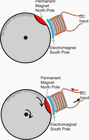
In the above shown diagram we see a disc with an embedded magnet at its edge (shown in red color) which is positioned with north pole facing outward, and also an electromagnet placed at a parallel proximity to the circular edge of the disc which produces a south magnetic field when energized.
Now assuming the arrangement is positioned as shown in the first upper diagram with the electromagnet in a deactivated state.
In this position as soon as the electromagnet is activated with an appropriate DC input it attains and generates a south magnetic field influencing a pulling force over the disc magnet which in turn forces the disc to rotate with some torque until its permanent magnet comes in line with the electromagnets opposite lines of flux.
The above action shows the basic format in which BLDC concept works.
How BLDC Motor Work with Hall Effect Sensors
Now let's see how actually the above concept is implemented using Hall effect sensors in order to sustain a continuous motion over the rotor.
The following example diagram explains the mechanism comprehensively:
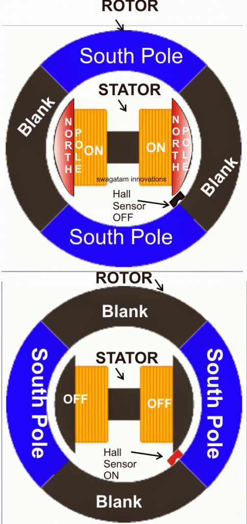
In the above diagram we basically see a straightforward BLDC rotor/stator arrangement, where the outer circular element is the rotating rotor while the central electromagnet becomes the fixed stator.
The rotor could be seen having a couple of permanent magnets fixed at the periphery which have south pole as the influencing lines of flux, the central stator is a strong electromagnet which is designed to generate an equivalent strength of North Pole magnetic flux when energized with an external DC.
We can also visualize a hall sensor situated near one of the corners of the inner rotor periphery. The hall effect fundamentally senses the magnetic field of the rotating rotor and feeds the signal to a control circuit responsible of powering the stator electromagnets.
Referring to the upper position we see the blank area (which is void of any magnetic field) of the rotor in close contact with the hall sensor keeping it in a switched OFF state.
At this instant, the switch off signal from the hall effect informs the control circuit to switch ON the electromagnets, which instantly induces a pulling effect on the rotor south pole standing just round the corner.
When this happens the South pole comes down surging producing the required torque on the rotor and tries to align itself in line with the north pole of the electromagnet.
However in the process the south pole of the rotor also pulls itself near to the hall sensor (as shown in the lower diagram) which immediately detects this and switches ON informing the control circuit to switch OFF the electromagnets.
Turn OFF Time of the Electromagnets is Crucial
Switching off of the electromagnets at the right moment as signaled by the hall effect sensor prohibits stalling and hampering of the rotor motion, rather allows it to carry on with the motion through the generated torque until the previous position begins shaping up, and until the hall sensor yet again "feels" the blank area of the rotor and gets switched OFF repeating the cycle.
The above toggling of the hall sensor in accordance with the various rotor positions inflicts a continuous rotational motion with a toque which may be directly proportional to the stator/rotor magnetic interactions, and ofcourse the hall effect positioning.
The above discussions explains the most fundamental two magnet, one hall sensor mechanism.
In order to attain exceptionally higher torques more magnets and sets of electromagnets are employed in other higher efficiency brushless motors wherein more than one hall effect sensor may be seen for implementing multiple sensing of the rotor magnets so that different sets of electromagnets could be switched at the preferred correct sequence.
How to Control BLDC Motor
So far we have understood the basic working concept of BLDC motors and learned how a Hall sensor is used for activating the motor's electromagnet through an external attached electronic circuit for sustaining a continuous rotating motion of the rotor, in the next section we will study regading how BLDC driver circuit actually work for controlling BLDC motors
The method of implementing a fixed stator electromagnet and a rotating free magnetic rotor ensures enhanced efficiency to BLDC motors compared to the traditional brushed motors which have exactly the opposite topology and therefore require brushes for the motor operations. The use of brushes makes the procedures relatively inefficient in terms of long life, consumption and size.
Disadvantage of BLDC Motor
Although, BLDC types may be the most efficient motor concept, it has one significant drawback that it requires an external electronic circuit for operating it. However, with the advent of modern ICs and sensitive Hall sensors this issue now seems to be quite trivial when compared with the high degree of efficiency involved with this concept.
4 Magnet BLDC Driver The Design
In the present article we are discussing a simple and basic control circuit for a four magnet, single hall sensor type BLDC motor. The motor operation may be understood by referring to the following motor mechanism diagram:
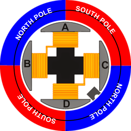
The image above shows a basic BLDC motor arrangement having two sets of permanent magnets across the periphery of an external rotor and two sets of central electromagnet (A,B,C,D) as the stator.
In order to initiate and sustain a rotational torque either A, B or C, D electromagnets must be in an activated state (never together) depending upon the positions of the north/South poles of the rotor magnet with respect to the activated electromagnets.
How BLDC Motor Driver Works
To be precise, let's assume the position shown in the above scenario with A and B in a switched ON state such that side A is energized with South pole while side B energized with North Pole.
This would mean that the side A would be exerting a pulling effect over its left blue North pole and a repelling effect on its right side south pole of the stator, similarly the side B would be pulling the lower red south pole and repelling the upper north pole of the rotor....the entire process could be then assumed to be exerting an impressive clockwise motion over the rotor mechanism.
Let's also assume that in the above situation the Hall sensor is in a deactivated state since it may be a "south pole activated" Hall sensor device.
The above effect would try to align and force the rotor such that the south locks on face to face with side B while the north pole with side A, however before this situation is able to transpire the Hall sensor is brought in a close proximity to the shifting upper south pole of the rotor, and when this just transits across the Hall sensor it is forced to switch ON, sending a positive signal to the connected control circuit which instantly responds and switches OFF electromagnets A/B, and switches ON electromagnets C/D, making sure that the clockwise moment of the rotor is yet again enforced maintaining a consistent rotational torque on the rotor.
Basic BLDC Driver Circuit
The above explained switching of the electromagnets in response to the Hall sensor triggering signal can be very simply implemented using the following straightforward BLDC control circuit idea.
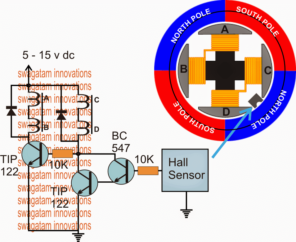
The circuit does not need much of an explanation since its too basic, during the switch ON situations of the Hall sensor, the BC547 and the coupled TIP122 is correspondingly switched ON which in turn turns ON the corresponding sets of electromagnets attached across their collector and positive, during the switch OFF periods of the Hall sensor, the BC547/TIP122 pair is switched OFF, but the extreme left TIP122 transistor is switched ON activating the opposite sets of electromagnet.
The situation is toggled alternately, continuously as long as power remains applied keeping the BLDC rotating with the required torques and momentum.


Questions & Answers
we are develope BLDC motor for our application, how you can assist me to design a right power for our appliccation.
Thank you for your assistance
BLDC motors require a specialized driver, which you can build by referring to the following posts:
https://www.homemade-circuits.com/?s=BLDC
respective sir this controller is comapatable for 48 volt 750 watt e bike hub motor pl tell me
Shuddhatam, The above circuit will not work for 48V ebike motor, you may have to apply one of the following designs:
https://www.homemade-circuits.com/?s=BLDC
Hello Mr Swagatam, Thank you very much for this great post.
Which brushless motor would you recommend to use when a thrust of approximately 3000g is required. Thank you very much.
Hi Peter, sorry I am not sure about it, because that may require some calculations
hi tank you