In this article we talk about a few simple yet accurate transistor tester circuits which can used to identify whether a transistor is good or bad.
Note: Please test *only* BJTs and MOSFETs (enhancement or depletion) with these circuits.
Simple Good/Bad Transistor Checker using a Single LED
Do you have a lot of strange old transistors in your rubbish drawer? You can tell what to retain and what to throw away with this straightforward little transistor checker circuit.
Simply determine the transistor type's base, emitter, and collector pinouts, adjust the slide switch to PNP or NPN, insert the device in place, and wait for the push buttons.
For medium to high gain transistors, pressing PB1 is going to turn on the LED. Press PB2 and the LED illuminate.
If it fails to illuminate or illuminates very dimly, it indicates a low-gain BJT. For the leakage test, press PB2. The LED need to be dimly or not lit at all.
Precision Transistor Tester using Op Amps
If you know a transistor's pinout, you can use this op amp based highly accurate transistor tester to quickly determine if it is good or bad and whether it is PNP or NPN. Additionally, certain common failure types are recognizable.
The focus of the design is on ease of use and simplicity, and it can function continuously for more than a month on a single PP3 battery. The tester will test bipolar transistors, however it is unable to work with FETs.
The tester is activated by pressing the iest button, which is actually the on/off switch, and the suspicious transistor is connected into a panel socket.
The two LEDs' condition displays the test outcome (Table 1).
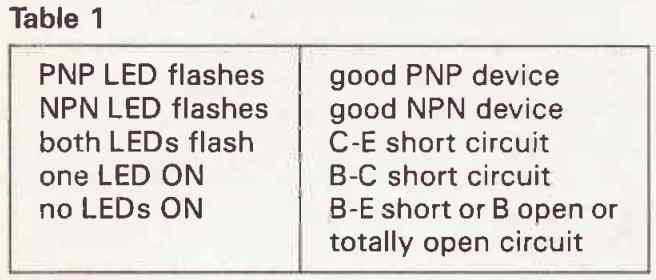
How the Circuit Works
The transistor under test's collector and emitter are subjected to fluctuating bipolar signals in a common base circuit by the tester, which causes current to flow in the LEDs while the transistor is conducting.
To differentiate between a dead battery and an open circuit transistor, a battery test button is provided.
If the battery is healthy, pressing this button will flash both LEDs to mimic a C-E short.
The tester utilizes an 8-pin dual op-amp chip, in my instance the IC 1458, which is dual 741's equivalent. However, various pin-compatible devices, such as the 353 dual J-FET amp, can be used in its place.
LED Specifications
In the end, I utilized two 0.2-inch green LEDs with the labels NPN and PNP as the indicators. A previous prototype employed a green LED for NPN and a red one for PNP, which appeared a lot better, but using intensity-matched LEDs is necessary if you are interested in a dual-colour display.
When I discovered that my new set of red LEDs used far more current than the green ones did, I gave up on the project.
Confirmed intensity-matched LEDs are more expensive; as a substitute, use red and green LEDs with the same average light output (measured in mcd: millicandelas) and in mA).
This is crucial because, once the battery is in place, the other LED might glow very faintly if a good transistor is being tested (owing to reverse conduction) or if the correct one is quite dim.
It could be perplexing.
How to Setup
The transistor tester may be set up in two different ways: a simple manner and a more complex yet dependable one.
Both times, the circuit is tested by simulating a C-E short (by pressing the battery test button), and the trimpot RV1 is adjusted until the circuit functions as needed.
At about 3Hz, the two LEDs should alternately flash. If not, you must have made some kind of error. Read on assuming they do.
The simplest method is to modify RV1 until the desired response is obtained for all devices while using a set of known perfect transistors.
BC184, BC274 (high gain NPN and PNP small signal), TIP31, TIP32 (3 A NPN and PNP medium gain power), and TIP3055, TlP2955 (15 A NPN and PNP low gain power) make up a common set.
The RV1 is in the nominal middle position.
Each transistor is placed into the socket one at a time, then the test button is depressed.
Then RV1 is steadily tweaked until the LEDs display the proper order. It's vital to utilize the transistors in the exact order: first, adjust the BC184 and BC214 until the tester indicates that both are accurate, then adjust the TIP31 and TIP32 more finely, and then tune the TIP3055 and T1P2955 to the tiniest degree possible.
Rechecking should then yield the right outcome using any transistor at random.
This setup technique has the drawback of not accounting for performance drift as the tester battery ages.
In a low current consumption like this circuit, a fresh PP3 may generate as much as 9.6V.
We want the tester to operate as long as possible on a single cell, say down to roughly 8V, which is as low as we actually dare.
Check Transistors without Removing them from the Circuit Board
This clever little checker circuit makes it possible to service transistors while they are still inserted within the circuit board.
To connect to a transistor's legs on the circuit board or wherever it is located, you can attach hook-type clips to the leads with the labels Base, Emitter, and Collector.
The transistor audio output transformer T1's secondary and C2's base-emitter feedback are both included in the circuit, which works like a straightforward feedback audio oscillator.
Whenever a good transistor is identified the oscillator becomes functional and the speaker generates a audio output. If the detected transistor is bad, no sound is generated from the speaker indicating a faulty transistor.
The R2 provides the base bias. The speaker could be a tiny 50 mm kind, but any speaker of a reasonable size would work; in fact, even the speaker's impedance is not really significant.
Universal BJT, JFET, MOSFET Tester Circuit
This useful transistor tester allows the user to quickly check the functionality of an NPN/PNP transistor, JFET or (V)MOSFET as well as determine the orientation of their terminals, or the pins appropriately.
A three-pin BJT or FET provides an overall 6 feasible correlated configurations, however just a single will likely be the right one.
This universal transistor tester circuit offers a easy and foolproof recognition of the appropriate transistor configuration as well as creates a practical examination of the transistor simultaneously.
How the Circuit Works
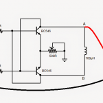
The tester circuit on its own includes a transistor that collectively with the transistor-under-test (TUT) forms an astable multivibrator circuit.
The tester features 5 testing slots in close proximity with each other, determined by their respective labeling:
E/S - B/G - C/D - E/S - B/G
This arrangement makes it possible for the below shown devices to be examined through the mentioned configurations:
• Bipolar Transistors: EBC / BCE / CEB, and reversed: BEC / ECB / CBE.
• Unipolar Transistors (FETs): SGD / GDS / DSG, and reversed: GSD / SDG / DGS.
The astable multivibrator stage of the circuit oscillates and blinks a bright white LED (Figure 1) whenever the transistor under test is connected the right way.
The LED could also flash if the E and C pins of the transistor are swapped, however the blinking speed is going to be faster.
This demonstrates the truth that a few varieties of BJTs can function even when their emitter and collector leads interchanged although with a performance characteristics that may be lower than in the normal configuration.
Testing JFETs
While testing JFETs having a symmetrical source and drain structure, it may be only feasible to distinguish the gate pin with any level of assurance, and the source and drain pins could be interchanged.
The load resistance of the transistor-under-test is constructed like a potential divider circuit with half the supply voltage by using resistors R3/R4. This enables an ordinary switch (S1) to swap from N(PN) to P(NP).
Using an LED Indicator
A flashing LED reveals proper positioning of the device under test! If the LED remains shut off or remains ON constantly indicates an incorrect configuration or dead, blown BJT.
This situation can additionally indicate that the unit being tested may be simply not a transistor.
The item could possibly, for instance, be a 3-pin voltage regulator, an SCR or a triac and so on.
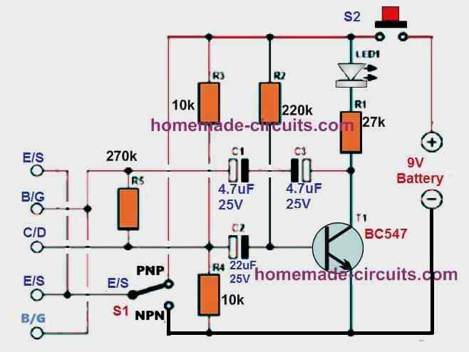
Using a Buzzer Indicator
The next variant of the universal transistor tester exhibited in the figure below employs a piezo buzzer instead of the LED indicator.
The frequency determining capacitor value in this design can be seen much reduced compared to the LED version in order to increase the oscillation frequency and make it audible.
A low volume buzzing sound from the buzzer signifies that the transistor is rightly inserted and is perfectly doing the job.
If there's no sound from the buzzer indicates that the BJT or the FET under test is either inserted incorrectly or it may be completely dead.
The push button allows you to switch the circuit on and check the transistor simultaneously as soon as it is hooked up.
The entire circuit can without any difficulty accommodate over a tiny piece of veroboard. Power supply can be obtained from a standard 9 V PP3 battery.
Simple NPN/PNP Transistor Tester Circuit using NOT Gates
Having difficulty finding which of the transistors in your trash box is PNP and which is NPN? No worries at all!
Here's a simple NPN PNP checker circuit which can be used to identify the respective devices effortlessly.
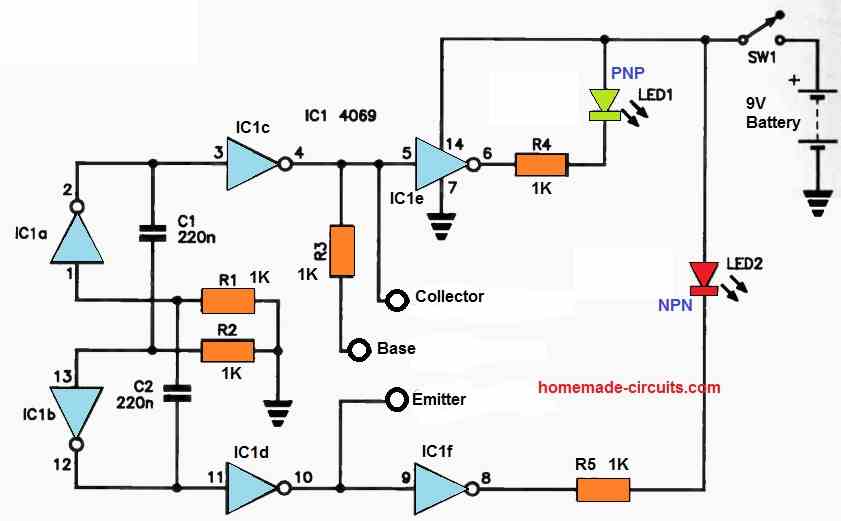
The NOT gate flip-flop in this circuit drives a few buffers, whose outputs power the two LEDS.
When an NPN device is connected, only LED2 illuminates and the drive to IC1c is blocked because the transistor conducts every time the output of IC1c is high.
The IC1a, IC1b flipflop oscillates at a very high frequency, and the persistence of vision guarantees that all you see is the LED's steady light.
When a PNP device is inserted, only LED1 lights, inhibiting the drive to IC1f since the device conducts whenever IC1d's output is high.


Questions & Answers
Hi Dear Swagatam;
These are the transistor legs measured value by diode mode TR is not removed from the circuit. Base to collector is about 0.816 and base to emitter is about 1.295 (too high). And there is no beep / no short between the legs. In the case is it possible to say it is normal / the TR is OK or do we still need to remove it for the test?
Hi Suat,
It is still a better idea to remove the BJT from the board for accurate results and confirmation. However, the difference in the values shows that the transistor may not be the best one, and might be be having some internal issues.
Hi Swagatam, I have just completed your Precision Transistor Tester.
Under your list of known test transistors the BC274 is not available in my country. Is there an alternative I use in its place?
Kind regards
Jan
Thanks Jan,
I think those transistor values are not too critical, any equivalent types can be used…you can use a BC557 instead.
Thanks Swagatam. l appreciate your assistance.
You are welcome Jan..
After further examining the LED-only circuit, I have more questions and ideas. Most of these also apply to the piezo-driver circuit.
1. The LED version of the tester can test LEDs: Install the LED in a socket.
2.I don’t recommend using these testers for a JFET. Reason: The circuits apply forward bias at Resistor R5. Forward bias can blow a JFET. (Even if the JFET doesn’t blow: Under positive bias, the device quits being a JFET, and won’t oscillate. It becomes a diode and a series resistor across the power rails.) Swagatam, please add a caution that one should *only* test bipolars and MOSFETs (enhancement or depletion) with these circuits.
3. Adding a JFET feature is possible, but would complicate the wiring. A resistor, a “JFET-S” terminal, and two capacitors would be necessary.
4. Isn’t Resistor R1 (27K) too large for LED visibility? With Transistor T1 saturated (ignoring the JD), the max LED current would be [(9-2) / 27K)], or 259µA. Some standard LEDs emit light down to 1 mA. Full brightness is typically 20 mA. I breadboarded the T1 circuit. In my test, a red, normal brightness LED didn’t light. I also tested a low-power (2 mA) green LED. It also failed to light. I then separately tried each LED in series with a 27K. I wired this circuit directly across the 9V source. Again, no light. Neither LED would light until I reduced the resistor value.
5. The R4 and R3 combination might load down the oscillator. As time allows, I will perform more breadboard experiments.
Thank you James,
I have added the note at the start of the article, as suggested by you.
Yes 27k looks too high for an LED to illuminate properly. It seems the circuit was designed by the elektor-electronics guys, and I wonder why they chose 27k as the limiting resistor for the LED. A 10k should be reasonably OK with a high bright RED LED.
Please feel free to share if you have further suggestions.
Swagatam,
Thanks for the clever and helpful circuits. A very similar transformer oscillator to your test circuit appeared in an Alvin Liff television book. This is a superb, basic go/no-go tester. Volume at the speaker may give some idea of transistor gain. (Less gain for power devices.)
On your Universal BJT, JFET, MOSFET Tester Circuit…
Usually, a Darlington can boggle a transistor tester. One of my homemade transistor/JFET testers can show that a Darlington operates. But the gain meter maxes out. The problem occurs because the bias resistors are wrong for a Darlington. The ‘right’ resistor would be ridiculously large. (I have a potential fix for this problem, but the fix is experimental.) I’ve seen Arduino-based testers fail to measure the complete gain. The subnormal measurement results because of internal speed-up resistors inside the Darlington.
Excellent work, Swagatam. Many thanks!
Thank you so much James, for your valuable suggestions, I appreciate them very much!
Actually the above article was submitted by an external author, so none of the designs are my own.
You are right, the PNP, NPN markings need to be reversed, and the B/S needs to be B/G. I will replace the diagram with a corrected one soon.
According to me, yes, a piezo buzzer could be also added across the collector of T1 and the positive line, it should work.
I have not yet tested this circuit, and I am not sure about the Darlington transistor response, however since the above circuit is a simple AMV why wouldn’t a Darlington work? In fact a Darlington requires 0.6V higher than a normal BJT to turn ON, that means they could be easily switched OFF and the oscillations could be easier to sustain. Many thanks for sharing your opinions, let me know if you have any further suggestions.
Hello Swagatam,
Under the first schematic, the following is stated:
“For the leakage test, press PB2. The LED need to be dimly or not lit at all.”
Shouldn’t it be press PB3 instead of PB2?
Yielding, (for good)
PB1 = LED On
PB2 = LED On
PB3 = LED Off or Dim
All of this Correct?
Thanks,
Ken
Hello Ken,
The explanation in the article is not given correctly sorry about that.
Here’s the correct explanation:
PB1 = for high gain, high hFE transistors.
PB2 = For transistors with low hFE such as low gain power transistors.
PB3 = to check how well the transistor switches OFF in response to a 0V base signal. If the LED fully shut off then the transistor is good with zero leakage.