In this article I will comprehensively explain everything regarding how to read and understand capacitor codes and markings through various diagrams and charts. The information can be used for identifying and selecting capacitors correctly for a given circuit application.
By Surbhi Prakash
Capacitor Codes and associated Markings
The various parameters of the capacitors such as their voltage and tolerance along with their values is represented by different types of markings and codes.
Some of these markings and codes include capacitor polarity marking; capacity colour code; and ceramic capacitor code respectively.
There are various different ways in which the marking is done on the capacitors. The markings’ format is dependent upon what type of capacitor is given.
The type of component acts as a deciding factor of the types of the codes used.
The component deciding the coding can be surface mount, technology, traditional lead, or capacitor dielectric component. Another factor which plays a role in deciding the marking is the size of the capacitor as it impacts the space which is available for capacitor’s marking.
The EIA (Electronic Industry Alliance) has also been playing a crucial role in providing standardized systems of marking the capacitors which can be followed as a standard in the industry.
Basics of Capacitor Markings
As discussed above, there are various factors and standards which are followed while marking the capacitors.
The various manufacturers manufacturing specific types of capacitors follow both basic or standard marking systems depending on the type of capacitor being manufactured and what is the best fit for it.
The marking “µF” is denoted by an abbreviation namely “MFD” on many occasions.
MFD is not used for denoting “MegaFarad” as is the general conception.
One can easily decode the markings and codes present on the capacitors if the person has a general knowledge of the marking and coding systems used for the capacitors.
The two types of general marking systems followed for marking the capacitors are:
Markings which are non-coded: one of the most common processes adopted to mark the parameters of a capacitor is to create a marking on the case of the capacitor or encapsulating them in some manner.
This is more feasible and suitable for capacitors of large size as it enables to provide enough space for creating the marks.
Capacitor markings which are abbreviated:
The capacitors which are small in size does not provide space required for clear markings and only few figures can be accommodated in the given space in order to mark it and provide a code for their various parameters.
Thus, abbreviated markings are used in such cases wherein three characters are used to mark the code of the capacitor.
There is a similarity between this marking system and the resistor’s color codes system which can be observed here, except for the “color” which is used in the coding system. Out of the three characters used in this marking system, the first two characters represent figures which are significant and the third character is representative of a multiplier.
In case the capacitors are tantalum, ceramic, or film capacitors, “Picofarads’ is used to denote the capacitor’s value; while in case the capacitor is of aluminium electrolytes, “Microfarads” is used to denote the capacitor’s value.
In case, small values with decimal points needs to be represented, then the alphabetical letter “R” is used such as 0.5 is represented as 0R5, 1.0 as 1R0, and 2.2 as 2R2 respectively.
This type of marking can be observed to be used more commonly in the surface mount capacitors where there is very limited space available. The different types of coding system used for the capacitors are:
Colour Code: A “colour code” is used in capacitors which are old. In the present times, industry rarely use colour code system except seldom on some of the components.
Tolerance Codes: The tolerance code is used in some of the capacitors. The tolerance codes used in the capacitors are similar to the codes used in the resistors.
Working Voltage Code of Capacitors:
The working voltage of a capacitor is one of its key parameter. This coding is used widely in various types of capacitors, especially for the capacitors which have enough space to write alphanumeric codes.
In other cases where the capacitors are small with no space available for alphanumeric coding, there is absence of voltage coding and thus any person handling such capacitors must take extra care when he/she observes that any kind of marking is absent on the storage container or the reel.
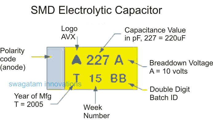
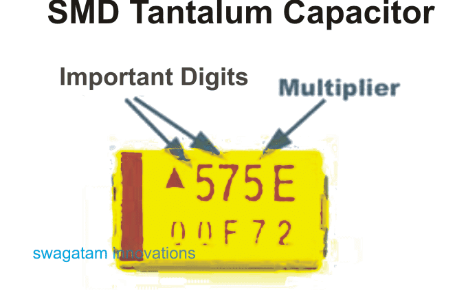
Some of the capacitors such as the tantalum capacitor and SMD electrolytic capacitor use a code consisting of one single character. This coding system is similar to that of the standard system followed by EIA and also requires very small amount of space.
Temperature Coefficient Codes: the capacitors required to be marked or coded in a manner which denotes the capacitor’s temperature coefficient. The temperature coefficient codes which are used for a capacitor are in most of the cases the standard codes given by the EIA. But there are other temperature coefficient codes which are used in the industry by different manufacturers, especially for capacitors including film and ceramic type of capacitors. The code used to quote the temperature coefficient is “PPM/ºC (parts per million per degree C).
Polarity Markings of a capacitor
The polarized capacitors require having markings denoting their polarity. In case the polarity markings are not provided to the capacitors, it may result in severe damage being caused to the component along with the entire circuit board.
Thus, utmost care needs to be taken to ensure that there are polarity markings on the capacitors when the latter is inserted into the circuits.
The polarized capacitors are in other words capacitors which are made of tantalum and aluminium electrolytes. A capacitor’s polarity can be easily determined if they are marked with signs such as “+” and “-“. Most of the capacitors which are circulating in the industry recently possess such markings. Another marking format which can be used for the polarized capacitors, especially electrolytic capacitor is the by marking the components with stripes.
A stripe marking denotes a “negative lead” in an electrolytic capacitor.
The stripe marking on a capacitor can also be accompanied by the symbol of an arrow pointing towards the negative side of the lead.
This is done when axial version capacitor is present where both ends of the capacitor consist of lead. The positive lead of a leaded titanium capacitor is denoted by the polarity markings on the capacitor.
The polarity marking is marked near the positive lead with a “+” sign indicating the marking. In case of a new capacitor, an additional polarity marking is placed on the capacitor to denote that the negative lead is shorter than the positive lead.
Different types of capacitors and their markings
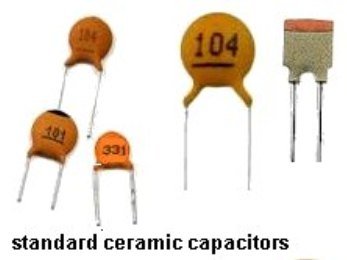
The markings on the capacitors can also be done by printing it on the capacitor. This is true for capacitors which provide enough space for marking to be printed and include film capacitors, disc ceramics, and electrolytic capacitors.
These large capacitors provide sufficient space to print markings which shows the tolerance, ripple voltage, value, working voltage, and any other parameter associated with the capacitor.
The differences between the markings and codes of the various types of lead capacitors are very minimal or marginal; but nevertheless these differences are many in number.
Markings on Electrolytic Capacitor: The lead type capacitors are manufactured in both large and small sizes. But the large leaded capacitors are more abundant.
Thus, for these large capacitors, the parameters such as value and others can be provided in detail instead of giving in abbreviated form.
On the other hand, for the smaller capacitors due to lack of sufficient space the parameters are provided in the form of abbreviated codes.
An example of the marking which can be typically observed in a capacitor is “22µF 50V”. Here, 22µF is the value of the capacitor while 50V denotes the working voltage. The marking of a bar is used to denote the polarity of the capacitor indicating the negative terminal.
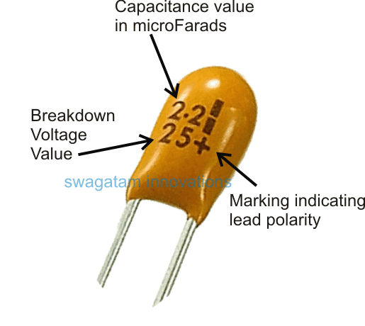
Markings of leaded tantalum capacitor: The unit, “Microfarad (µF)” is used to mark the values in the leaded tantalum capacitors. An example of a typical marking observed on a capacitor is “22 and 6V”. These figures indicate that the capacitor is of 22µF and 6V is its maximum voltage.
Markings of Ceramic Capacitor: The markings on a ceramic capacitor are more concise in nature since it is smaller in size as compared to electrolytic capacitors.
Thus, for such concise markings many different types of schemes or solutions are adopted. The value of the capacitor is indicated in “Picofarads”. Some of the marking figures which can be observed are 10n which denotes that the capacitor is of 10nF. In a similar way, 0.51nF is indicated by the marking n51.
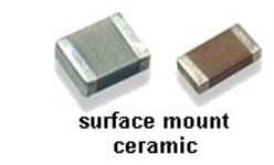
Codes of SMD Ceramic Capacitor: The capacitors such as surface mount capacitor do not have sufficient space available for markings due to their small size.
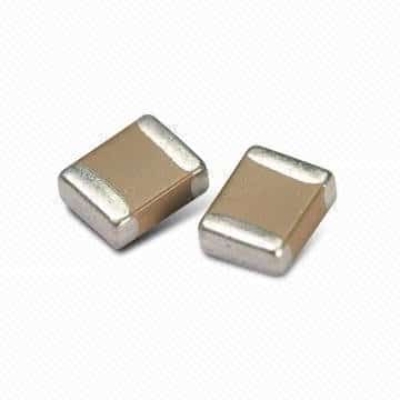
The manufacturing of these capacitors are done in such a manner that any type of marking is not required. These capacitors are loaded in a machine called pick and place which eliminates any marking need.
Markings of SMD tantalum capacitor: Similar to the ceramic capacitors, there is absence of markings which are observed in some of the tantalum capacitors.
The tantalum capacitors only consist of the polarity markings. This is present in order to ensure the correct insertion of the capacitor in the circuit board.
The marking format consist of three figures is generally used for the capacitors which has sufficient space available such as is evident in the ceramic capacitors.
The marking of a bar can be observed in some of the capacitors across their one end denoting the capacitor’s polarity.
The marking for polarity is important in order to identify and check the capacitor’s polarity since the destruction of the capacitor can occur if the polarity is not known and a person places it in reverse biasing, especially in the case of tantalum capacitors.
It is utmost important that one can identify, read, and check a capacitor’s value.
Since there are a range of capacitors available and their different coding and marking systems, it is quintessential that a basic understanding of these marking and coding is there to an individual in order to apply it appropriately to respective capacitors.
An individual can determine the capacitor’s value with practice and experience and just going through few examples mentioned here would not suffice.
Capacitor Color Code Chart
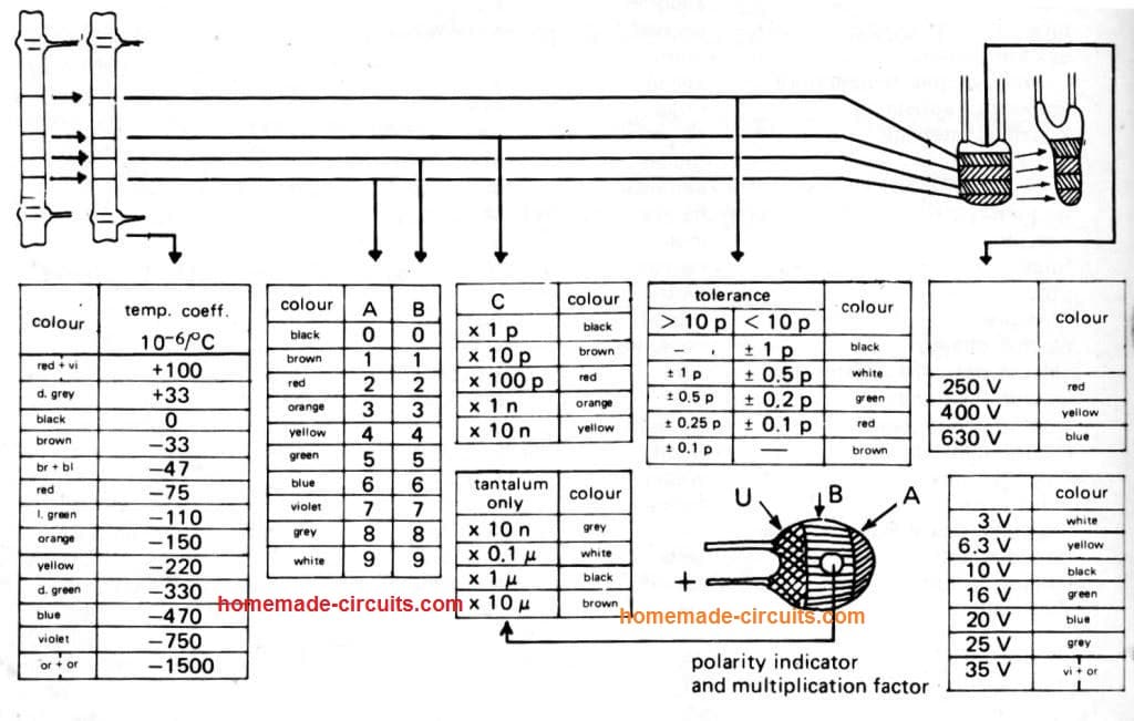
1. Temperature Coefficient Table
| Color | Temp. Coefficient (10^-6/°C) |
|---|---|
| Red + Violet | +100 |
| Dark Grey | +33 |
| Black | 0 |
| Brown | -33 |
| Brown + Blue | -47 |
| Red | -75 |
| Light Green | -110 |
| Orange | -150 |
| Yellow | -220 |
| Dark Green | -330 |
| Blue | -470 |
| Violet | -750 |
| White + Orange | -1500 |
2. Capacitor Color Codes (A, B, C Bands)
| Color | A (Digit) | B (Digit) | C (Multiplier) |
|---|---|---|---|
| Black | 0 | 0 | x1 p |
| Brown | 1 | 1 | x10 p |
| Red | 2 | 2 | x100 p |
| Orange | 3 | 3 | x1 n |
| Yellow | 4 | 4 | x10 n |
| Green | 5 | 5 | |
| Blue | 6 | 6 | |
| Violet | 7 | 7 | |
| Grey | 8 | 8 | |
| White | 9 | 9 |
3. Capacitor Tolerance Levels
| Tolerance | Color |
|---|---|
| > 10 p | Black |
| ±1 p | Brown |
| ±0.5 p | Red |
| ±0.25 p | Orange |
| ±0.1 p | Yellow |
| ±0.05 p | Green |
| ±0.02 p | Blue |
| ±0.01 p | Violet |
| ±0.005 p | Grey |
| < ±0.002 p | White |
4. Capacitor Voltage Ratings
| Voltage Rating | Color |
|---|---|
| 250 V | Red |
| 400 V | Yellow |
| 630 V | Blue |
5. Tantalum Capacitor Ratings
| Voltage Rating | Color |
|---|---|
| 3 V | Grey |
| 6.3 V | Black |
| 10 V | Brown |
| 16 V | Red |
| 25 V | Orange |
| 35 V | Violet + Orange |

Questions & Answers
Hello, I have a starter and alternator tester, made by OTC, model judge 2. About a week ago, my power company must have had a power surge, because when I woke up several of my circuit breakers had been tripped. After resetting the breakers, most things worked again. The circuit that the tester is on is in my garage, where I have ground fault interuption outlets. The ground fault outlet had tripped. After resetting, as soon as I plugged the tester in, it immediately tripped again. I took apart the unit control, and I saw that a capacitor had blown. and half of the coating is gone, The capacitor goes across the hot and neutral where the power enters the unit. I’m assuming that it is a X type safety capacitor. It is a round blue dipped disc type. There appears to be 3 lines of Identification. but all I have is the right half. The top line looks like it ends in “NR”, second line is “221U”, and the bottom line appears to be “Q30”. As I said I only have the right half, so I can’t tell what the first half would be. Any help you can give me would be VERY greatly appreciated. Thank you, Doug Vaughn
Hi, that part is most likely an MOV, not a capacitor, you can check out this article:
https://www.homemade-circuits.com/how-to-select-mov/
You can simply remove that part and check the response, whether the circuit-breaker still trips or not….
I should also mention that the motor and power supply do not work at the same time, Each one is for a different test. Thanks
Thank you Swagatam, for your quick response. After reading the article about MOV’s, I believe you are correct. I removed the component from the circuit, and it did not trip. The circuit does nothing, so I need to replace the MOV. Going by the numbers I posted, can you guess as to what value MOV I can use. It is a 120 volt system, This board controls a power supply that puts out approx. 150 amps at 12 volts. The board also controls a 1/2 HP motor. The MOV that I pulled out is a little smaller than a dime. Thanks again for your help, Doug
Sounds Great! Thanks for updating the results Doug.
In that case you can try any of the following variants, which I found online upon searching a “200V clamping voltage MOV”:
ZOV-10D121K (ZOV): 10mm disc, Varistor Voltage: 120V, Clamping Voltage: 200V.
EPCOS B72207S0750K101 (TDK): 7mm disc, 75V AC, 100V DC, Clamping Voltage: 200V.
Eaton MOVS4032V075: 4032 SMD case, Maximum Clamping Voltage: 200V.
Multicomp Pro MPV10D121KNK: 10mm disc, Clamping Voltage: 200V.
Thanks Swagatam, I have ordered the 10dk121k, When it comes in I will install and let you know what happens. Thanks again
Sounds great Doug, wish you all the best!!
Absolutely fabulous; many thanks; have a great day today.
Ted
Have become confused about capacitor types and values. The one I’m currently interested in (within the power supply board of a Samsung TV) is shiny brown with the following markings;
334J 400V
8 912 NPP
Would appreciate what type of capacitor it is and it’s value
Thanks in anticipation
That capacitor is a polypropylene film capacitor, often written as PP or NPP (Non-Polarized Polypropylene).
The marking 334J 400V means the following.
334 means the capacitance value. This code translates to 330 nF, which is 0.33 µF.
J indicates the tolerance, which is ±5 percent.
400V means the capacitor is rated to safely handle 400 volts DC.
The second line 8 912 NPP is mostly manufacturer and batch information. The important part here is NPP, which again confirms it is a non-polarized polypropylene film capacitor.
i have a capacitor with no polarity markings (nos strips, no signs). its only state the company, the voltage and the uf and the temperature. i notice a slight difference in the lead length, one is slightly longer than the other. I am still not able to confirm whether it’s a polarized or non-polarized
If the markings on the capacitor are not worn out, and it is without any polarity marking from the manufacturer, then surely it is a non-polar capacitor.
Good morning. Writing from the Los Angeles area. Am attempting to resurrect a little used tile wet saw I purchased new in 1994. A K-Diamond model 2.5 hp motor that has ceased to turn on or even hum.
All wiring in-tact and functional as I checked with tester.
Has been non-running for some 8-10 years now. I believe it likely is the start or run capacitor. Am trying to find one with little luck as of yet. These are the markings on the grey colored 4 connector on top 5 7/8″ tall x 1 7/8″ diameter capacitor case:
SH Capacitor
cap70mfd
W.V.400V.A.C
DRE marking in a triangle stamped on the case
Any thoughts where I can find a replacement capacitor? Thank you for any assistance or clarity as I search for my own repairs.
Hey, that looks like old type motor start capacitor, 70uF 400V rating. You can use any new 70uF or 75uF capacitor with 400V or 440V AC rating, that will work same. Just check size and wire terminal before fitting. You can search on Amazon or eBay for “70uF 440V motor capacitor” or visit any local motor rewinding shop, they will give you one easily. Most probably after replacing that, your motor will start running again.
Hi Swagatam:
I’m working on a Sony sound bar, mod. HT-CT260H that won’t turn on. It could be any component within, but I’m hoping that it could be a capacitor ZHN #s (M) 105° C, 250V, 150uF. It registers 166 volts and not the 250 volts AC.
Is it possible, that may be the problem? Where can I get such an item?
Hi Tim,
The 250V capacity of the capacitor is a DC value, not AC, and it indicates the max tolerance capacity of the capacitor, beyond which it can burst or blow off. So 250V is not the level it is supposed to maintain.
If your input AC is 120V, then the 166V after rectification and filtration by the specified capacitor might generate around 166V, which is perfectly fine.
But if the input AC is 220V then something else might be causing the drop in the voltage, which will need to be diagnosed.
However, if you find the capacitor bulged or leaking then you it might be better to change it.
Thanks for your reply. That capacitor is good then. There’s no other visual indication any other of the capacitors on the boards are suspect. I’m afraid I’ll just have to look for a comparable sound bar. There are too many micro components in there that’s beyond my capacity. However, I won’t give up just yet.
Yes, if that capacitor is working as the mains filter capacitor and your input AC is 120V, then that capacitor appears to be good. Otherwise, you may have to dig deeper, probably check the semiconductor devices, which can fail silently.
Hello Swagatam! Can you tell me the source for your graphic giving the capacitor colour codes? I’ve found many that are similar, but yours is the only one I’ve seen that gives, in the temperature coefficient list for ceramic capacitors, two different values (110 and 330) for two different shades of green.
Thanks from Texas,
Andy
Thank you Andy,
However, since this post was published by many years ago (10 years), so unfortunately I do not seem to remember the source of the original article.
Hello Swagatam. I have a PCB with a SMD capacitor marked “DLC271”. Can you help me with this?. Thanks in advance.
Hello Jorge,
Sorry, I could not identify this capacitor value. I tried searching this online but could not find any information about this specific part. The alternative way could be to identify the value using a capacitance meter.
Thanks for your reply and time. I will keep searching.
Hello Swagatam,
I have a light green mica (guess..) capacitor found in a Ten Tec 509 transceiver. Line one = 106. Line two = 0.01/20. Line three = 400V. I am not having any luck figuring out line two. Can you clear that up for me, please?
Thanks,
Ted.
Hi Ted,
Even I cannot figure out that number in the second line.
It is confusing, because the first line indicates the value as 106 pf which should be = 10uF
But the second line shows 0.01 which may indicate 0.01uF
The 400 V is perfect, which clearly indicates the maximum tolerable voltage of the capacitor = 400 V.
Hi Swagatam hope you are very well.
How do I know if a ceramic cap is C0G (NPO) or just a normal MLCC
The marking is 222 and it is a typical brownish yellow bulb like an MLCC
Thank you for your help
A normal MLCC (multi-layer ceramic capacitor) may use different types of dielectric materials, such as X7R or Y5V, which have a higher capacitance change with temperature, voltage, and time compared to C0G (NPO) capacitors. These types of capacitors may have different markings, depending on the manufacturer, but they typically do not have “C0G” or “NPO” markings
Thank you very much for replying and that is good to know.
What is the best way to test if a Cap is C0G or MLCC with a DMM?
To test whether a capacitor is a C0G or MLCC using a Digital Multimeter (DMM), there are a few steps you can follow:
Set your DMM to measure capacitance. This setting is usually denoted by the unit “F” or “μF” on the dial.
Discharge the capacitor by shorting its leads together with a wire or a resistor for a few seconds.
Connect the DMM leads to the capacitor’s terminals, observing the polarity.
Take a measurement of the capacitance value.
Remove the DMM leads and let the capacitor discharge again by shorting its leads together.
Wait a few minutes, and then measure the capacitance again.
If the capacitance value does not change significantly between the initial and second measurements, then the capacitor is likely a C0G capacitor. C0G capacitors have very low temperature coefficients, which means that their capacitance value does not change much with temperature. If the capacitance value changes significantly between the initial and second measurements, then the capacitor is likely an MLCC.
Hey Swagatam
I am very grateful to you for your carefully explained suggestion. My dmm does have a capacitance measuring setting so I will give it a try. Hope you have a great weekend. Best wishes.
You are most welcome Benjamin.
Hi Swagatam
Thank you that is very helpful.
Is there a good way to test to find out with a dmm?
Hi Benjamin,
I don’t think a capacitor value or its characteristics can be checked using a DMM.
Hello. I am trying to identify three components without any luck doing research online. Think it must be Tantalum Capacitors.
Following markings on top.
#1: 10710P
#2: CS7F
#3: AA86
Can anybody help identify?
Thanks
Bous
I am also having difficulty in understanding the values, hope somebody else is able to figure them out.
Correcting the previuios question…. capacitor rating was in error
I am trying to figure out proper ratings for a ceramic capacitor. The markings are as follows:
S 14
K 275
RU
19 33
So it is 2.7 UF +/- 10% capacitor.
I cannot figure out the volts on it. Also it is difficult to find 2.7 UF capacitor. What rating (higher or lower) capacitor can I use? Does the voltage rating matter? The board has an input of 220vac.
That is not a capacitor, but a varistor aka voltage-dependent resistor (VDR).
By default the voltage rating of all ceramic capacitor is 50V. You can use 2.2uF if you cannot find 2.7uF
The voltage rating of a capacitor should be ideally 1.5 times higher than the supply DC of the circuit. For example if the supply DC is 12V, then all capacitors must have a voltage rating higher than 20V….so higher voltage rating is not a problem, but it must be at least 1.5 times the DC supply of the circuit.
If the circuit supply is 220V then the capacitor values must be 400V.
I am trying to figure out proper ratings for a ceramic capacitor. The markings are as follows:
S 14
K 275
RU
19 33
So it is 27.5 UF +/- 10% capacitor.
I cannot figure out the volts on it. Also it is difficult to find 27.5 UF capacitor. What rating (higher or lower) capacitor can I use?
The minimum voltage rating for all ceramic capacitors is 50 V by default.
For a 27.5uF you can connect a 22uF capacitor in series with a 4.7uF capacitor
Swagatam, trying to find what capacitors I have. Cannot locate any source. They are marked sk taiwan. One has two wires both black with 4L 250wv.ac. The other is 4 wires with two yellow on one end and the other end has pink wire at 4uf and grey at 5uf. At each is imprinted 1/2w330k.AC 250v.ac. I think these could be resistors built into the capacitor. Any thoughts are appreciated. Gerald
Hi Gerald, sorry I have never come across such capacitors with multi terminals, so unable to suggest anything at this moment.
LGU155k 250 MER on Radial Cap. What does MER denote? LGU is Manufacturer I understand the Other code specs. But can not fine any reference for the suffix MER
MER are non-inductively wound with Metallized Polyester film as dielectric and electrode with copper-clad leads and epoxy resin coating.
i Have a htx100 bought in 1990 the electrolytic caps read 1M890, 1M1906, 1M8914, etc I cannot find any where on the net that speaks about these kinds of numbers system.
Can you help me. the whole radio is like this, every electrolytic cap.
1M8914 would be.
1M 70V DC.
89.1nf (8.91*10^4).
You’re welcome.
I tried searching online but could not find any info, so can’t suggest much about it…
Thanks for your quick reply and your time.
Bob w7utp
Great article! I have noticed some capacitors have other numbers on them, for instance a 10mF 370V also says “40/70/21”, among other things. Can you explain what the numbers with the slashes mean?
-40 degrees celcius/+70 degrees celcius operating range. The last number I ended up here trying to figure out myself.
Glad you liked it, sorry I can’t figure out the value of the number that you have mentioned
Hi dear, I’m a mechanical engineer in Los Angeles and do some hobby stuff too,
I was wondering if you know the value of this capacitor:
226A
63E80
is yellow surface mount and I thing is made by AVX
Thanks!
226A = 22uF/10V
63E80 could be 63.8uF 25 V
Thank you Sir. that is correct, the numbers 63E80 are on the same cap. I guess as you described it in article about cap markings it should be the year and a lot number.
All the best!
Glad to help Kami!
Hi Swagatam – I am trying to figure out the value for a cap in an audio amp. It is black, 1 1/4″ wide, 2″ tall. The only markings are the polarity strip and M0007
Using a meter I get 4.8 mF, but I am not able to figure out if that is a correct value from the very limited markings on it.
Any suggestions?
Hi Todd, if you have checked it by removing it from the circuit board then it must be correct, because a standard Capacitance meter will always give the correct results. The M0007 appears to be some kind of insulation code, which cannot be used for getting the value of the cap.
sir i mean that the capacitors used in ceiling fans are they film or metallised capacitors
thanks sir.
they could be non-polar electrolytic type
sir can I use capacitor used in ceiling fan as a snubber capacitor for a motor controller , i mean a kind of capacitor used to reduce voltage spikes in motor controller
Abioye, according to me there’s no problem in doing that, you can use it.
thanks for the post sir……it's very helpful…
you are welcome soumen!!