• Skip to main content
  • Skip to primary sidebar

Homemade Circuit Projects

Get free circuit help 24/7

New Projects | Privacy Policy | About us | Contact | Disclaimer | Copyright | Videos | Circuits for Beginners | Basic Circuits | Hobby Projects | Transistor Circuits | LED Drivers 

You are here: Home / 555 IC Circuits / Cyclist’s Safety Light Circuit – Nighttime Visibility for Cyclists, Walkers, Joggers

Cyclist’s Safety Light Circuit – Nighttime Visibility for Cyclists, Walkers, Joggers

Last Updated on July 6, 2019 by Swagatam 2 Comments

caution electricity can be dangerous

A simple flashing bicycle safety light circuit has been discussed in the following article

In many occasions when we happen to go down the road at night, it is normal to meet cyclists that are visible only when they might be within walking distance.

In case you're a bike aficionado and prefer to stroll in the dark or overnight, this rider's safety light circuit can be very useful, since it will likely be easily observable.

Circuit Operation

We have observed designs that are based on two integrated circuits 555 and 12 diodes LEDs red, but I was able to modify the design to use only 555. With this particular new made it was easy to double on the 2 groups design. LEDs (see diagram) really do not persist the same time, but that does not create much of  a problem.

Operational details of the bicycle safety light circuit

Utilizing only one circuit 555, it could be configured as an astable multivibrator (having a square waveform) for the operations.

This circuit will have two groups of 6 LEDs each.

The top group of 6 LEDs will light any time the output of 555 is low (approximately 0.75 volts) and the top group would probably switch on when the output of 555 is high (approximately 8.4 volts

This alternating light motion is very spectacular and very hard to overlook the night.

LEDs can be placed in various different optional ways:

- Two rows of LEDs as shown in the diagram,
- Two rows interspersed with LEDs, and therefore the first group is switched on but with 3 up and 3 down and then in the second group, etc..

This circuit was created to be used with a PP3 9 volt battery

Circuit Diagram

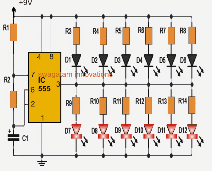
Parts list for the discussed bicycle safety light

IC1: 555 timer
D1 through D12:  red LEDs  5mm
R1: 10K resistor
R2: 100K resistor
R3 to R14: 1K 1/4 watt
C1: 10uF/25V

You'll also like:

  • 1.  2-Pin Motorcycle Turn Signal Flasher Indicator Circuit with Beeper
  • 2.  Tennis Ball Throwing Machine Circuit
  • 3.  3 Simple DC Motor Speed Controller Circuits Explained
  • 4.  Adjustable CDI Spark Advance/Retard Circuit
  • 5.  RC Helicopter Remote Control Circuit
  • 6.  CMOS IC LMC555 Datasheet – Works with 1.5 V Supply

About Swagatam

I am an electronic engineer (dipIETE ), hobbyist, inventor, schematic/PCB designer, manufacturer. I am also the founder of the website: https://www.homemade-circuits.com/, where I love sharing my innovative circuit ideas and tutorials.
If you have any circuit related query, you may interact through comments, I'll be most happy to help!

Reader Interactions

Comments

    Have Questions? Please post your comments below for quick replies! Comments should be related to the above artcile Cancel reply

    Your email address will not be published. Required fields are marked *

  1. adesina temiloluwa says

    January 28, 2015

    welldone sir…i really appreciate your effort here i just completed an inverter project designed by u in diz link… https://www.homemade-circuits.com/2013/04/how-to-modify-square-wave-inverter-into.html?m=1. i used ne555 pwm for the Choping of d square wave…..it powers my tv,cfl even 60 watt bulb …just want to show appreciation… am gratefull
    temiloluwa from Nigeria.

    Reply
    • Swagatam says

      January 28, 2015

      Thank you Adesina, I appreciate your efforts too. keep it up.

      Reply

Primary Sidebar

Calculators

  • 3-Phase Power (15)
  • 324 IC Circuits (19)
  • 4017 IC Circuits (52)
  • 4060 IC Circuits (25)
  • 555 IC Circuits (98)
  • 741 IC Circuits (19)
  • Arduino Engineering Projects (83)
  • Audio and Amplifier Projects (114)
  • Battery Chargers (82)
  • Car and Motorcycle (94)
  • Datasheets (46)
  • Decorative Lighting (Diwali, Christmas) (33)
  • Electronic Components (100)
  • Electronic Devices and Circuit Theory (36)
  • Electronics Tutorial (116)
  • Fish Aquarium (5)
  • Free Energy (34)
  • Fun Projects (13)
  • GSM Projects (9)
  • Health Related (20)
  • Heater Controllers (29)
  • Home Electrical Circuits (102)
  • How to Articles (20)
  • Incubator Related (6)
  • Industrial Electronics (28)
  • Infrared (IR) (40)
  • Inverter Circuits (98)
  • Laser Projects (12)
  • LED and Light Effect (93)
  • LM317/LM338 (21)
  • LM3915 IC (25)
  • Meters and Testers (65)
  • Mini Projects (148)
  • Motor Controller (67)
  • MPPT (7)
  • Oscillator Circuits (26)
  • PIR (Passive Infrared) (8)
  • Power Electronics (34)
  • Power Supply Circuits (77)
  • Radio Circuits (10)
  • Remote Control (48)
  • Security and Alarm (61)
  • Sensors and Detectors (120)
  • SG3525 IC (5)
  • Simple Circuits (75)
  • SMPS (29)
  • Solar Controllers (60)
  • Timer and Delay Relay (53)
  • TL494 IC (5)
  • Transformerless Power Supply (8)
  • Transmitter Circuits (40)
  • Ultrasonic Projects (16)
  • Water Level Controller (45)

Calculators

  • AWG to Millimeter Converter
  • Battery Back up Time Calculator
  • Capacitance Reactance Calculator
  • IC 555 Astable Calculator
  • IC 555 Monostable Calculator
  • Inductance Calculator
  • LC Resonance Calculator
  • LM317, LM338, LM396 Calculator
  • Ohm’s Law Calculator
  • Phase Angle Phase Shift Calculator
  • Power Factor (PF) Calculator
  • Reactance Calculator
  • Small Signal Transistor(BJT) and Diode Quick Datasheet
  • Transistor Astable Calculator
  • Transistor base Resistor Calculator
  • Voltage Divider Calculator
  • Wire Current Calculator
  • Zener Diode Calculator

© 2023 · Swagatam Innovations