A very interesting push button operated fan regulator circuit with LED display is explained in the following article, which can be built and installed at home for the suggested purpose. The idea was requested by Mr. Sriram KP.
The Design
Normally all fan regulators whether it's a mechanical or electronic employ a rotary kind of switch for the speed control operations. The mechanical type of fan regulators typically use a clicking type of rotary switch while the electronic ones mostly can be seen with a smoothly adjustable Pot type of control.
Although the electronic versions are more efficient than the mechanical variants, these lack the ability to display the speed levels accurately and furthermore the pot control feature looks quite outdated, technology wise.
The proposed push button fan regulator circuit with display discussed in this post utilizes PWM control for controlling the speed of the fan and enables the user to do the same using an up, down push button arrangement. Additionally the design also offers a 10 LED speed level indicator in response to the button operations.
Circuit Operation
The circuit can be understood with the following explained points:
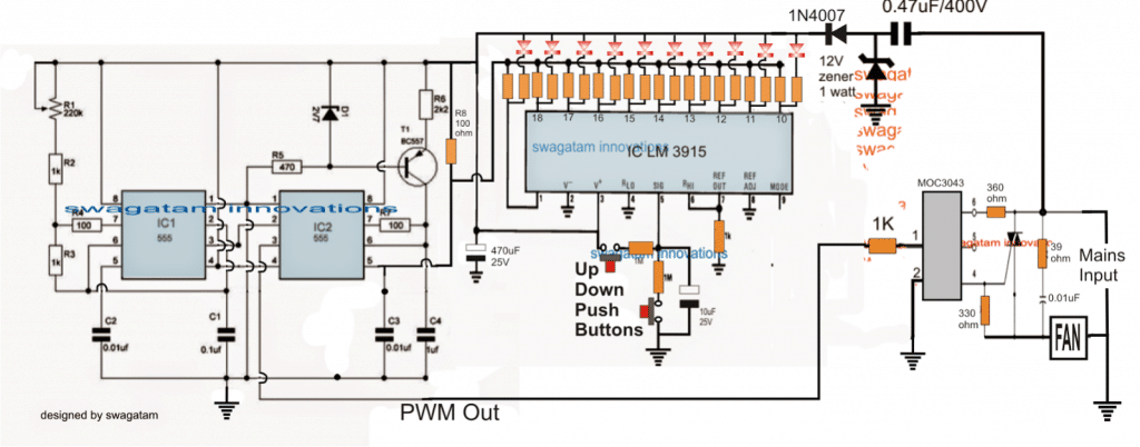
The 555 IC1 is configured as a clock generator, and the second 555 IC2 as a PWM generator circuit.
The high frequency clocks generated by IC1 is fed to pin#2 of IC2 which is used by IC2 for generating triangle waves at its pin#7
The triangle waves at pin#7 of IC2 is compared by the potential difference at its pin#5 to generate the corresponding PWMs at its pin#3.
Depending on this potential difference, the PWM output at pin#3 is adjusted into narrow pulses (for lower potentials) and wider pulses (for higher potentials).
The above potential difference at pin#5 is derived from the outputs of the IC LM3915, which is a dot/bar mode LED sequential driver IC.
Here this IC is configured as an up/down push button driver circuit. Pressing the relevant buttons enables its outputs to sequence with a logic low from pin#1 to pin#10 and vice versa.
The resistors across these outputs which are associated pin#5 of IC2 are arranged in an gradually incrementing manner from pin#10 to pin#1, such that pin#1 has the highest value resistor and pin#10 the lowest value resistor.
The highest value resistor could be a 6K8 and the lowest value could be a 100 ohm, while the other in between should gradually and proportionately selected and distributed across these values.
The LED resistors can be all 1K resistors.
Thus when one of the push buttons is arbitrarily pressed such that the output sequence moves across one of the outputs, the resistor at this output in conjunction with R8 generates a particular potential difference at pin#5 of IC2 which in turn determines the PWM width at pin#3 of IC2.
This PWM is then fed to a specialized triac driver optocoupler IC MOC3043, which reads the PWMs through its LED's average intensity and drives the connected triac accordingly rendering the corresponding amount of AC on the connected load.
The connected load here being a fan, causes the fan to rotate at the specified speed, in accordance with the fed PWM.
The LED display responds to the push button pressing and jumps across the outputs of the LM3915 in an up/down manner as long as the button is in the depressed mode, and settles down to the selected pinout as soon as the respective button is released.
Thus the LED indicates the speed level while the corresponding potential divider created at this pinout determines the PWM level at pin#3 of IC2 which is subsequently forwarded to the triac driver optocoupler.
The entire circuit of rthe above explained push button fan regulator is powered from a simple stabilized transformerless power supply using the shown 0.47uF capacitor, a 12V zener diode and a 1N4007 diode.


Questions & Answers
yes sir….but we don’t have time sir …it’s compulsory to submit our mini project within 24th April…already 90% work is completed…..only we want the value of resistors……please sir….
Hello Achhu, I understand, but how will you submit if it doesn’t work? You should have asked me once, then I could have advised you correctly. There are around 5% circuits in this blog which may have problems and I am gradually sorting them out. This circuit is one of them.
I can still give you a foolproof circuit which will work 100% if you want it.
I can give you the values but the LM3915 stage won’t work as expected in the design
sir how to calculate that resistors values?
Hello, did you read my previous comment? Please read it!
sir already we are done with 80 percent of circuit connection…what can we do sir?
sir please give any suggestions….
sir how to calculate that resistors value sir..?
Acchu, The LM3915 is having problems, since it is not holding the LED in one place, it slowly starts shifting away, it’s not stable.
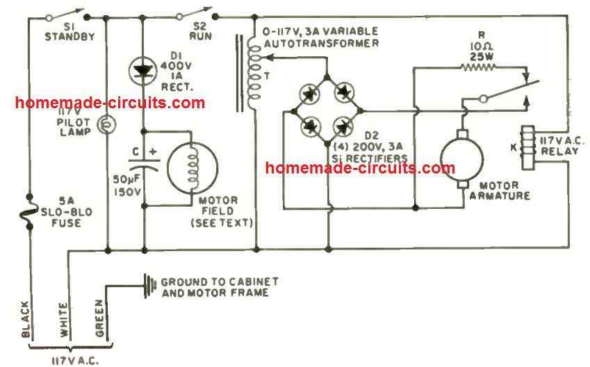
Instead you can try the second circuit from this article:
https://www.homemade-circuits.com/simple-remote-controlled-fan-regulator/
But even this is not practically confirmed, but I am sure it will work, I may try it today or tomorrow for confirmation.
We have to replace the IR sensor section with a single push-button.
But this circuit will not provide up/down operation, in this circuit the user can select the speed upwards and then back to zero and then upwards. Meaning if you reach the speed #3 you cannot go to #2 in one step…you will have to go back to zero and then come to #2.
are all the 20 resistors are 1 k resistors ?
sorry all are not 1K, the positive line resistors will need to be calculated incrementally, but this design is not yet tested and therefore unconfirmed, let me test it first and then the readers can try it.
sir what is the value of that resistors which are connected with led to IC?
Those are 1k resistors
Nice project.
I want to control 1KW exhaust FAN with Optocoupler – Triac circuit via arduino PWM signal.
Sir, can please you post any relevant solution .
thanks for your reply.
I have tested opto-triac circuit with MOC3021 and BT136 via Arduino PWM .It was working perfectly ,but the thing is it is not capable for high wattage Load (above 1.5KW).
the limiting resister is burning ( in your circuit, the resister connected on MOC’s pin 6).
my question is ,shall I used higher wattage TRIAC (ex BT139) or shall i remove the limiting resistor?
OK then it’s fine…you can try replacing the low value triac with BT139, and replace the 360 ohm with a lower value such as 220 ohm, and check the response…if it still doesn’t fire then you can reduce the value further down until the response is optimal.
also make sure to increase the 330 value proportionately
Manish, as we know that triac cannot be controlled with PWM, however if the PWM is thrown in the form of timed bursts then probably it might work, as done in time proportional PWM control, so if the Arduino is programmed to do this then may be it will work…
https://www.homemade-circuits.com/2016/10/triac-phase-control-using-pwm-time.html
I want 8 channel decimal to binary encoder with 7 segment (or LED diodes)display provided that the inputs done through single push button switch. Thanks in advance.
will the speed be the same where it was left before power cut in case power goes off and resumes back
ok. Thank you very much.
NPN will not work, you can use any low power PNP transistor in that position.
Thanks. What will be the modifications in case the transistor T1 is replaced by an npn one please?
it's for operating pin#7 of IC2 with a constant current so that the PWMs are always constant even under voltage fluctuations.
What is the role of transistor T1 please?
yes if a "memory feature" is introduced using a high value capacitor etc..
Sir please tell me TV cable booster circuit.
Sir I am new to using an optocoupler. My question is why we need to connect external triac at the output of optocoupler??? Because optocoupler has an internal photon trigger triac, based on the illumination of led triac will be operated then why we need to provide an external triac. Suggest some other tutorial for me sir. What is the rating of triac choosen for optocoupler
Vijay, the opto internal triac is a low power triac and is employed for triggering the external high power triac through zero crossing detection, it cannot handle high power loads directly that's why an external triac becomes necessary
the external triac rating can be as per the load current specs….
In the above diagram, In MOC3043, pin2 is connected to ground, fan's right side is connected to ground and fan's left side also connected to ground. The Traic's down pin also connected to ground. So if the whole power is ON means will it be any short circuit on the line? Is the last MOC3043 circuit is a correct one? Am confused. Kindly help.
I have corrected the diagram, please check it now.
Thanks. Will try.What is the rating for the zener diode D1 and cap C4 ? and can u conform that cap C4 is a non-polar?
D1 can be 250mW…and C4 can be a 25V cap
C4 need not be a non-polar, electrolytic will also do.
ok. In the right side of MOC IC, 360 Ohms is connected to the TRAIC from pin 6 of the IC. 360 Ohms is not available in my area. Can I use 330+33 ohms or 330 ohms instead of that 360 Ohms? If I use only 330 Ohms instead of 360R, will it make any prob in the circuit?
the value is not critical, 330 ohms will also work, the network is only to provide some sort of protection to the triac from transients, if the load is an inductive load.
Is there any voltage specification for 0.01uf and watt for 39R which is connected is series between the fan and the phase?
And TRAIC's T1 is connected to fan, T2 to phase and gate to pin 4. Won't be any problem if TRAIC is directly connected to phase? Bcoz I read in an article that TRAIC should not be connected to phase directly. If connected means the TRAIC will burn out. Is that correct?
yes 0.01 needs to be 400V rated and PPC type.
39 can be a 1/4 watt resistor
since the load is in series with the triac, the triac can never burn.
Thanks. Can I use mylar cap (Polyester) for 0.01uf/400v ?
mylar will do….
Sir great work,
Sir can you help me making PWM circuit for Hydrogen generator.
Thanx in advance.
thanks Taibani,
you can try the following design, just replace the motor with your HHO generator
https://www.homemade-circuits.com/2012/05/make-this-pwm-based-dc-motor-speed.html
Ok. Can I use IC MOC3041 or IC MOC3083 or IC MOC3063 instead of IC MOC3043? IC MOC3043 is not available in my area.
Could u pls tell me how to adjust the R1 to get 150Hz or more than 150Hz? which is the best frequency to set? and how to conform that am getting these much frequency? Any experiment or calculation is there?
any MOC IC will do.
150 Hz is not crucial…you can use a 150k fixed resistor instead of the pot
don't forget to connect all the "earth" marked lines together, in common.
CIRCUIT IS NOT ISOLATED FROM MAINS.
Thanks for the circuit. Am going to implement it. Can u tell me the rating for all the resistors and diode D1 ?
and what is the use of R1 as VR?
At what value I have to set that POT R1?
Then what is the name and rating of the TRIAC which is connected at IC MOC3043?
Whenever the rating is not mentioned, it's always 1/4 watt.
R1 is for determining the number of chopping or the frequency of the PWM, it's not crucial but must be at least 150Hz.
The triac can be a BT136