• Skip to primary navigation
  • Skip to main content
  • Skip to primary sidebar

Homemade Circuit Projects

Get free circuit help 24/7

  • +1000 Circuits
  • Hobby Circuits
  • Basic Circuits
  • Learn Arduino
  • Logic IC Pinouts
  • Disclaimer
You are here: Home / Inverter Circuits / Transformerless UPS Circuit for Computers (CPU)

Transformerless UPS Circuit for Computers (CPU)

Last Updated on March 13, 2019 by Swagatam 8 Comments

In this post we discuss how to build a simple UPS circuit for backing up computers or PCs during sudden power failures or brownouts.

Introduction

Normally when we talk about uninterruptible power supplies (UPS) we imagine large inverter units with complex features, where it imperatively needs to be a pure sine wave type. Such inverters occupy enormous spaces, require bigger batteries and are immensely expensive.

A little innovative thinking shows that the above cumbersome design can be replaced by just batteries and a small circuit for implementing all the necessary actions of an efficient compact transformerless UPS circuit.

However the design also a few downsides. It is specifically intended for CPU type computers only and cannot be used for other applications.

The installations procedures are complicated and time consuming and requires expertise in the field of electronics as well as computers.

Having said these, once installed the unit will provide some very useful services for a very long perid of time. Moreover the efficiency of the system will be far better than the conventional UPS systems.

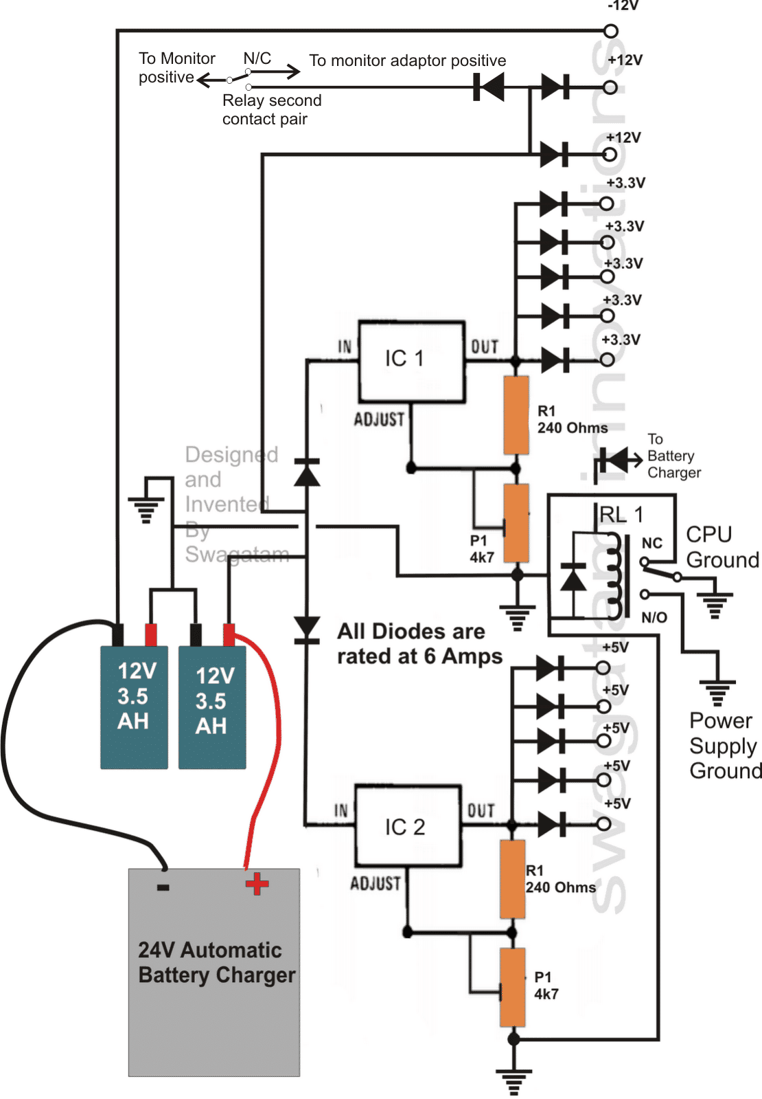
Looking at the circuit we see that its all about switching the motherboard of the CPU with a set of matched outputs from a battery source which exactly corresponds to the voltages that's obtained from the power supply of the CPU.

Using the Versatile LM338 ICs

The circuit is made up of two ICs LM338, which are set for producing exact 3.3V and 5V outputs which are appropriately bifurcated into many outputs via diodes.

The 12V outputs are taken directly from the battery, while a minus 12V output is derived by employing an extra battery.

One battery feds the LM338 circuit while the other battery generates the required -12V output for the CPU.

The switching action is implemented by a relay when power fails.

The relay simply selects the appropriate grounds while doing the reverting actions.

As long as power is available from the mains, the relay keeps the backup ground disconnected from the CPU ground, and keeps the power supply ground connected to the CPU ground via  the N/C contacts.

The relay is powered by an external AC mains power supply source, which is also used for charging the batteries. Actually it can be an automatic battery charger unit, attached to the system for the required actions.

The moment AC fails, the relay disconnects the power supply ground from the CPU and connects the back up circuit ground with the CPU ground, so that the CPU now gets the required back up from the relevant outputs of the transformerless inverter circuit.

The reverting actions is done within a few ms, providing an interruptible power during power failures or brownouts.

All the outputs shown in the circuit should be carefully soldered to the relevant wires of the power supply by slightly stripping the wire insulation and then taping them. The voltages must be thoroughly confirmed before integrating the two systems together.


Part List

IC1, IC2 = LM338
R1, R2 = 240 Ohms,
P1, P2 = 4K7 presets
All diodes are 6 amp rated
Relay = 24V, SPDT
Battery as shown


SHARING IS CARING!


Previous: How to use Eagle CAD
Next: Make This 1KVA (1000 watts) Pure Sine Wave Inverter Circuit

About Swagatam

I am an electronic engineer (dipIETE ), hobbyist, inventor, schematic/PCB designer, manufacturer. I am also the founder of the website: https://www.homemade-circuits.com/, where I love sharing my innovative circuit ideas and tutorials.
If you have any circuit related query, you may interact through comments, I'll be most happy to help!

You'll also like:

  • 1.  1500 watt PWM Sinewave Inverter Circuit
  • 2.  Maintenance Tips for Lead Acid Battery
  • 3.  Inverter Voltage Drop Issue – How to Solve
  • 4.  Arduino Full-Bridge (H-Bridge) Inverter Circuit
  • 5.  How to Calculate Ferrite Core Transformers
  • 6.  Low Battery and Overload Protection Circuit for Inverters

Please Subscribe (Only if you are Genuinely Interested in our Newsletters)


Reader Interactions

Comments

    Your Comments are too Valuable! But please see that they are related to the above article, and are not off-topic! Cancel reply

    Your email address will not be published. Required fields are marked *

  1. Search Related Posts for Commenting

  2. Απόστολος Παπαστεργίου says

    The above circuit Transformerless UPS Circuit for Computers (CPU)

    Reply
    • Swagatam says

      yes it can be used after doing the recommended wiring correctly

      Reply
    • Απόστολος Παπαστεργίου says

      can you tell me how to connect the purple +5VSB and gray POWER OK .

      Reply
      • Praveen says

        +5VSB and gray POWER OK is standby voltage used to trigger and switch on for SMPS ATX

        Reply
        • Swag says

          sorry, I am not sure about it at the moment, I don’t remember, because the circuit was designed by me 3 years ago

          Reply
    • Swagatam says

      sorry I do not have much idea regarding computer internal wiring details…

      Reply
  3. apostolos says

    helo mr.Swagatan majumbar i have try to make the circouit Transformerless UPS Circuit for Computers (CPU)
    and i have some problems can you help me please
    when the supply returns and disconnect the battery the PC stops.

    Reply
    • Swagatam says

      hello apostolos, which circuit diagram are you referring to?

      Reply


Primary Sidebar

Electronic Projects Categories

  • 3-Phase Power (15)
  • 324 IC Circuits (19)
  • 4017 IC Circuits (51)
  • 4060 IC Circuits (25)
  • 555 IC Circuits (94)
  • 741 IC Circuits (18)
  • Amplifiers (49)
  • Arduino Engineering Projects (82)
  • Audio Projects (85)
  • Battery Chargers (76)
  • Car and Motorcycle (88)
  • Datasheets (45)
  • Decorative Lighting (Diwali, Christmas) (32)
  • DIY LED Projects (82)
  • Electronic Components (97)
  • Electronic Devices and Circuit Theory (35)
  • Electronics Tutorial (99)
  • Fish Aquarium (5)
  • Free Energy (34)
  • Games (2)
  • GSM Projects (9)
  • Health Related (17)
  • Heater Controllers (24)
  • Home Electrical Circuits (98)
  • Incubator Related (6)
  • Industrial Electronics (27)
  • Infrared (IR) (39)
  • Inverter Circuits (94)
  • Laser Projects (10)
  • LM317/LM338 (21)
  • LM3915 IC (24)
  • Meters and Testers (55)
  • Mini Projects (153)
  • Motor Controller (65)
  • MPPT (7)
  • Oscillator Circuits (15)
  • PIR (Passive Infrared) (8)
  • Power Electronics (33)
  • Power Supply Circuits (65)
  • Radio Circuits (9)
  • Remote Control (46)
  • Security and Alarm (56)
  • Sensors and Detectors (116)
  • SG3525 IC (5)
  • Simple Circuits (72)
  • SMPS (29)
  • Solar Controllers (60)
  • Timer and Delay Relay (51)
  • TL494 IC (5)
  • Transformerless Power Supply (8)
  • Transmitter Circuits (39)
  • Ultrasonic Projects (12)
  • Water Level Controller (46)

Follow Homemade Circuits

Facebook
Twitter
YouTube
Instagram
My Facebook-Page
Quora

Feeds

Post RSS
Comment RSS

Circuit Calculators

  • AWG to Millimeter Converter
  • Battery Back up Time Calculator
  • Capacitance Reactance Calculator
  • IC 555 Astable Calculator
  • IC 555 Monostable Calculator
  • Inductance Calculator
  • LC Resonance Calculator
  • LM317, LM338, LM396 Calculator
  • Ohm’s Law Calculator
  • Phase Angle Phase Shift Calculator
  • Power Factor (PF) Calculator
  • Reactance Calculator
  • Small Signal Transistor(BJT) and Diode Quick Datasheet
  • Transistor Astable Calculator
  • Transistor base Resistor Calculator
  • Voltage Divider Calculator
  • Wire Current Calculator
  • Zener Diode Calculator
  • Privacy Policy
  • About Us
  • Contact
  • Disclaimer
  • Videos – Circuit Test Results

© 2021 · Swagatam Innovations