The explained circuit of a water level controller circuit is based on a adjustable timer circuit whose time delay is first adjusted to match the filling time of the tank, as the the tank fills, the timer delay also simultaneously lapses and its output switches OFF the water pump.
Circuit Specifications
Actually the circuit was requested to me by Mr. Ali Adnan who is one of the fans of this blog. Let's first hear what he had to say:
I like your blog very much. I have a problem which i think is common in every home, the problem is: I have a Water Pump (which pulls water from bore) installed at my home, when my brother switch on the water pump he always forget(u know bhulakar one:P) to switch it off back:( and water tank gets over flowed and water runs in upper portion of our house:(
I want you to help me to design a timer circuit to automatically turn off the pump at given time. I am not expert in electronics but i like to play with electronic and knows very well how to solder and always trying to do some little experiments with help of your blog. Please provide me the circuit for above sited problem with complete parts list and diagram.
Designing the Proposed Water Level Controller with Timer
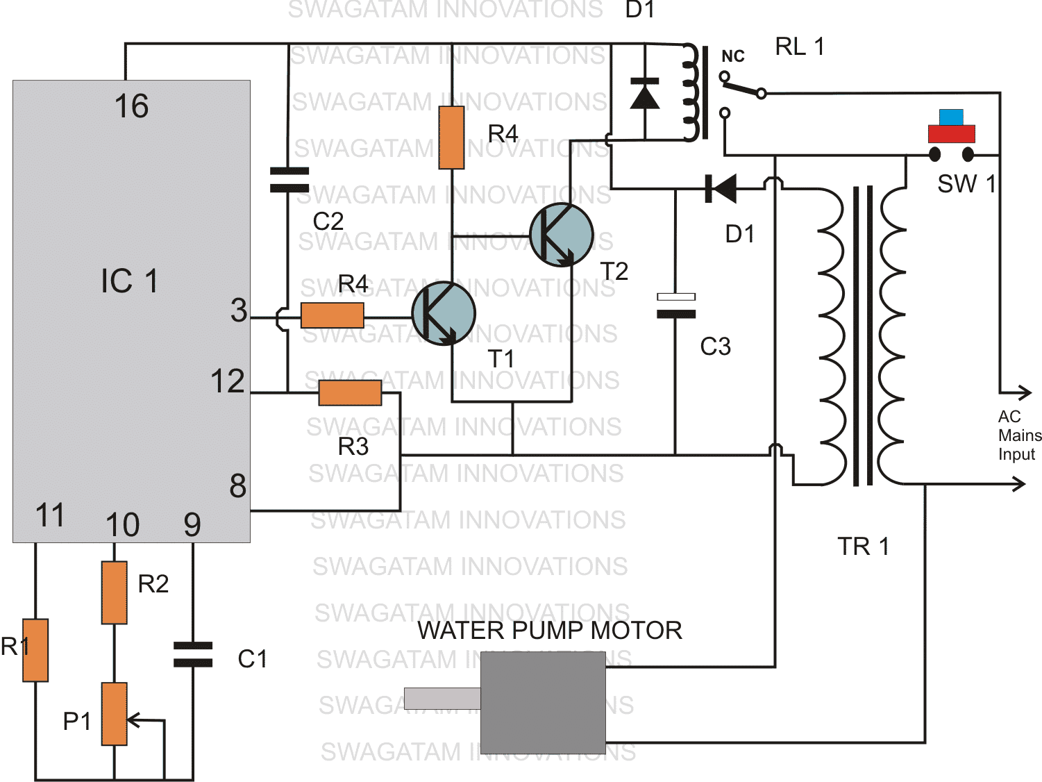
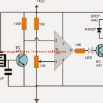
The CIRCUIT DIAGRAM of this water level timer controller circuit utilizes a single versatile IC 4060 for generating the required time delay.
P1 is initially adjusted through some trial and error so that it exactly matches the filling time of the water tank which needs to be monitored.
The circuit is initiated by pressing the push button SW1 when the N/O contacts of the relay are bypassed.
This momentarily switches ON the transformer which powers the IC instantaneously.
This instantly triggers the transistor and also the relay which takes over and latches ON the circuit.
Now the circuit holds ON even after the push button is released, everything happens within half a second.
The above operation also simultaneously switches ON the pump motor which starts pushing water in the tank.
Once the timer counting finishes, pin #3 becomes high, T1 conducts and switches OFF T2 and the relay.
The relay contacts reverts to its original state switching OFF the motor as well as the the entire circuit, halting the motor pump and hopefully inhibits the tank from overflowing.
Parts procured by Ali Adnan
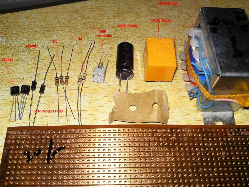
Parts List
- R1, R3 = 1M, 1/4 watt CFR
- R2 = 10K, 1/4 watt CFR
- R4(T1 base) = 22K, 1/4 watt CFR
- R4(T2 base) = 10K, 1/4 watt Cfr
- P1 = 1M preset horizontal
- C1 = 1uF/25V
- C2 = 1uF/25V non polar, any type will do
- C3 = 1000uF/25V
- D1, D2 = 1N4007,
- Relay = 12V/SPDT/contact current as per motor specification
- SW1 = Bell push type of button
- IC1 = 4060
- T1 = BC547
- T2 = 8050, or 2N2222
- TR1 = 0-12V/500mA
The above automatic water level controller with timer circuit was also built and appreciated by Mr.Raj Mukherji, one of my friends and a keen follower of this blog. I have explained more about his experience with the circuit.
Hi Swagatam,
Thank you very much for the timer circuit.
I have made the prototype on a general purpose PCB and so far found it to work accurately for my purpose: 5 min, 10 min and 15 min delay respectively (with the P1 set at 15.4 Kohms for 5 min delay etc). I am planning this weekend to house it in a 4x6 box and test it on actual load.
So far, I was looking at the above comments and would like to add something regarding the question raised by Mr. Khan on the relay. For my purpose, I am intending to use this timer on an AC 50 Hz, 220 - 240 volts, Crompton Greaves self priming mono-set pump, type - Miniwin II, 0.37 Kwatt/0.50 HP. So, I have purchased a 12 volt SPST relay which has a contact current tolerence of ~7 Amps. I think this is sufficient for my purpose and also for any kind of small pumps/loads. Isn't it?
I will definitely share with you the picture of the completed project.
Thank you,
Kind regards,
Raj Kumar Mukherji
My answer to Raj:
Hi Raj,
That's great! Thank you very much for the update.
A 7amp contact would mean a maximum capacity of 7*220 = 1540 watts, that's probably more than sufficient for the purpose.
I am sure the pictures that you will send will be loved by the other readers also, so please do send them here for publication.
Yes, surely the link will be very useful for the readers who would want to learn the timing calculation more accurately.
Thanks and Best Regards.
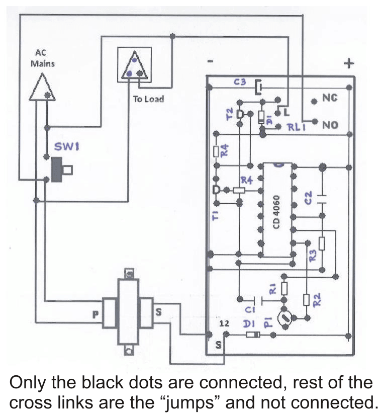
PCB Layout for the Above Circuit, Designed and Submitted By Mr. Raj Kumar Mukherji:
(Component-side view)
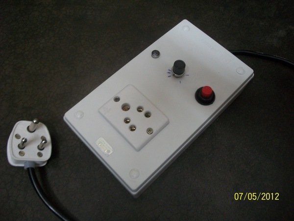
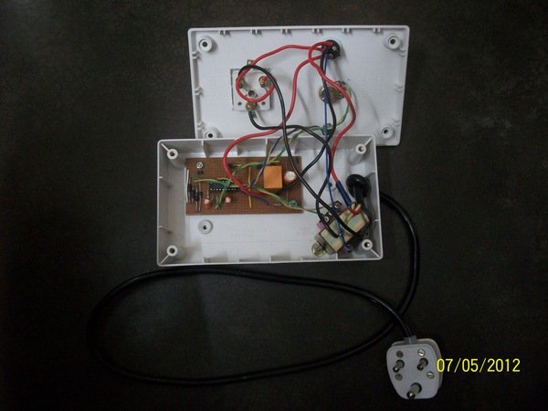
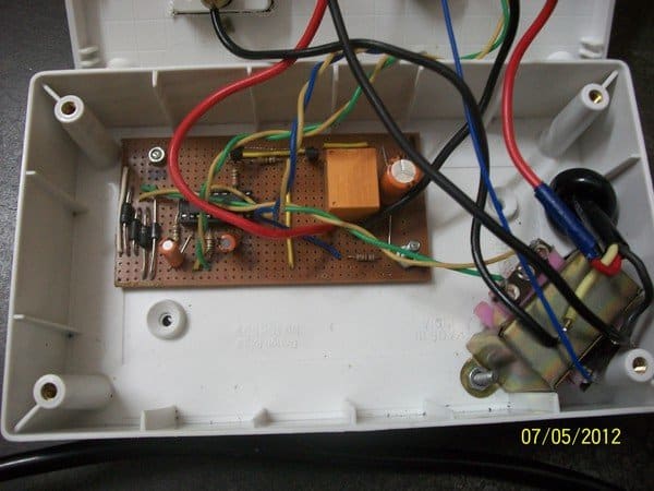
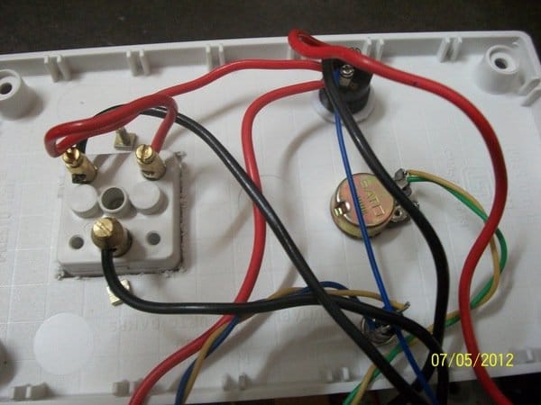
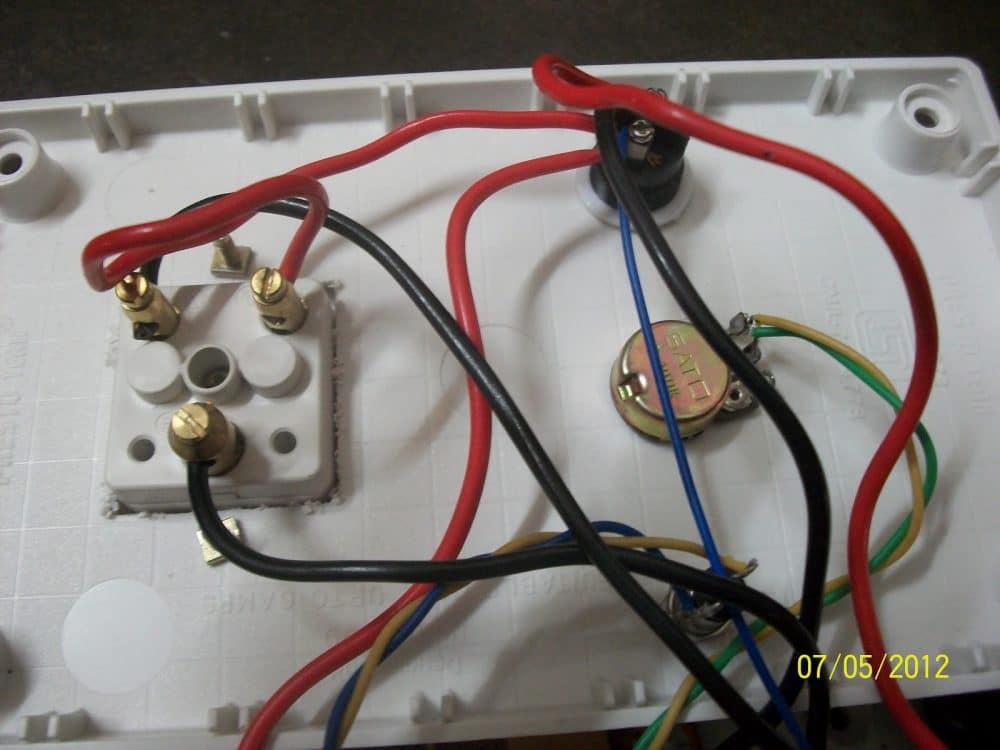
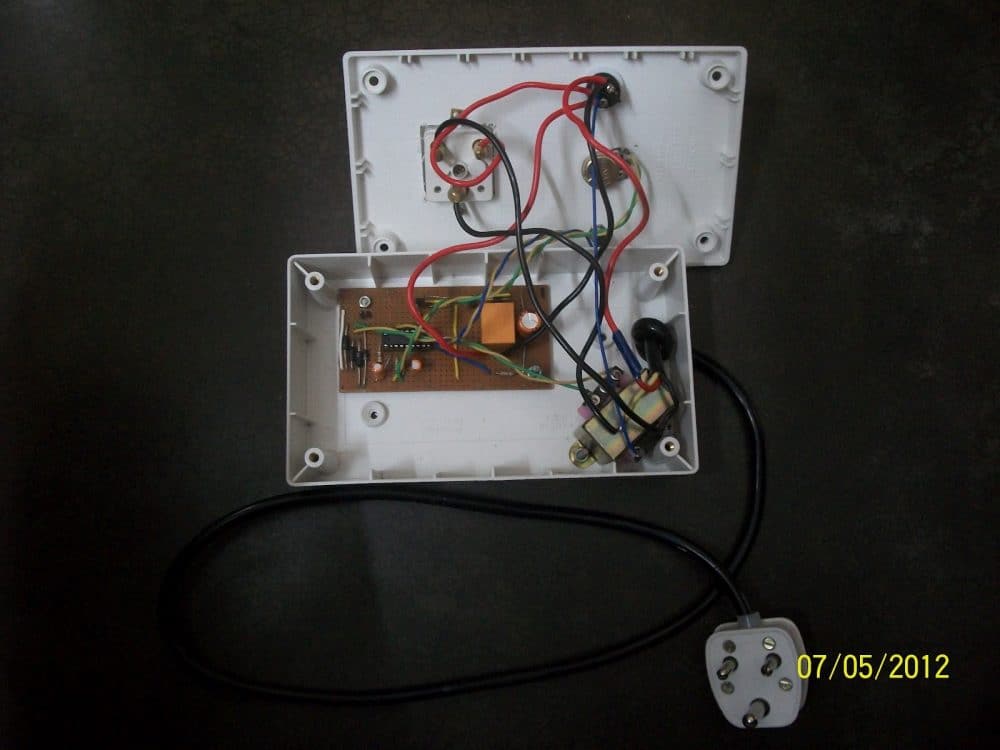
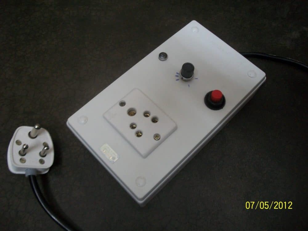
Pictures of the completed water level timer controller prototype, sent by Mr. Raj Kumar Mukherji:

The proposed water level timer/controller circuit was further modified and enhanced Mr.Raj Mukherji, who is also an avid reader of this blog, and a keen electronic enthusiast.
Here's the feedback email that he sent to me explaining everything regarding the working of the circuit:
Finally I have managed to build, the model of this timer based water level controller project which is given below:

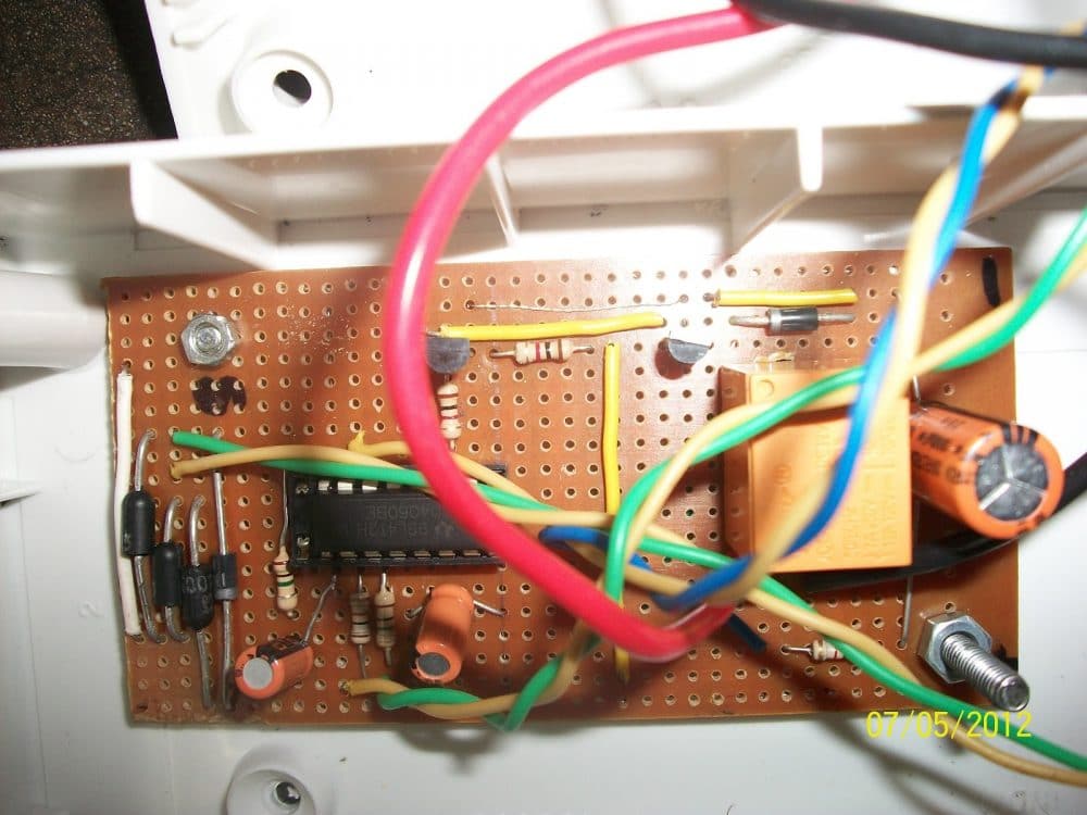
There were only three modifications I made:
1. Connected an LED to pin 7 in order to get a visual indication of the oscillation.
The LED starts to blink after 20 secs of powering the timer on
2. Used four diodes for full wave rectification instead of just a single diode for
smooth DC input
3. Added 22Mfd capacitor between pin 12 and 16 instead of 0.22Mfd because 0.22Mfd was
not allowing the oscillation to begin when the circuit was drawing power from the
transformer. However, 0.22Mfd did not make any problem when the power was fed from
a 9 Volt battery
I have found that with the given values of the R and C, the range of this timer is between 1 - 30 mins.
I have also found the formula to calculate the frequency of the timer (it is found to work correctly to a certain extent practically):
F in KHz = 1 / {2.3 x (R2+P1) x C1} where, R2 & P1 in K Ohms, C1 in Mfd
1 Time Period (TP) in milisecs = ------------ where, F in KHz, Q(n) as shown below. {F / Q(n)}
Pin7 = Q(4) -> divided by 16 Pin5 = Q(5) -> " " 32 Pin4 = Q(6) -> " " 64 Pin6 = Q(7) -> " " 128 Pin14 = Q(8) -> " " 256 Pin13 = Q(9) -> " " 512 Pin15 = Q(10) -> " " 1024 Pin1 = Q(12) -> " " 4096 Pin2 = Q(13) -> " " 8192 Pin3 = Q(14) -> " " 16384
Example: If P1 is set at 15 KOhms, R1 = 1 KOhm, C1 = 1 Mfd and we select the output from Pin3 (which is Q14) then:
1 1 1 F = -------------------- = ------------------ = ------------ = 0.0272 KHz {2.3 x (R2+P1) x C1} {2.3 x (1+15) x 1} 36.8
where, F = Clock frequency of the timer
Then, the frequency at Pin3 of the IC will be: 0.0272/16384 = 0.00000166 KHz
Therefore, Time Period (TP) of the timer is: 1/0.00000166 = 602409.6 miliseconds = 602.41 secs = 10.04 mins
[NOTE: Time Period = ON time + OFF time]
Hope this will help my co-readers to understand the working of the CD 4060 better.
Thank you,
With warm regards,
Raj Kumar Mukherji
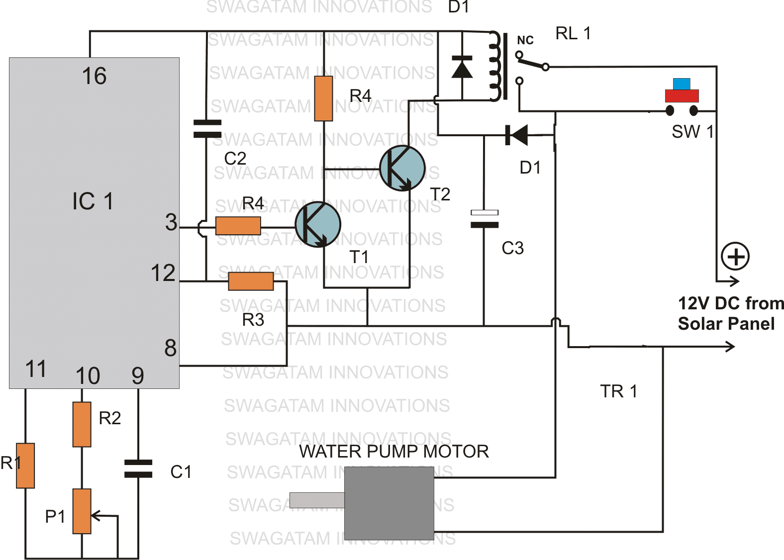
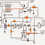
Upgrading the Water Level Timer for Solar Panel Operation
The following diagram shows how the above circuit may be used with a solar panel supply, and with a DC motor connected at the output. The design was requested by Mr. Mehmet

Questions & Answers
Hello swagatam,
My name is Jerome from Uganda.
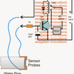
I am trying to build a dry run protection for my DC water pump.
I built a simple water activated switch with a latched relay. when the water is finished in the well and it switches off the pump but when the water level reaches the probe it immediately starts the pump without allowing it to regain a certain Volume.
Help me design a circuit that when water reaches the probe it delays some time before switching the pump on somewhere from 15 to 30 minutes.
Thanks in advance.
Best regards.
Hello Jerome, you can replace the existing relay circuit with the following circuit:
the parts R2 and C2 can be tweaked to change the delay time….
Hello man, i am an electronics engineering student on his last year and would want to learn like you to do this exciting timer flow level controller! Please communicate with me and can give some rewards too,
Thanks!
Sir,
I built this circuit as indicated in the circuit diagram. I’m facing one issue i.e., The relay latches perfectly when I push the bell switch and the relay continues to be latched and never turns off even if I set the 100K pot to as low as 1K.
My relay coil resistance is about 160ohms, hence I’m using BC547 as T2. Please guide me.
Regards,
Jagan S
Hello Jagadish, please connect an LED across pin#14 to ground or pin#15 to ground, and check whether it is flashing with different rates or not in response to the pot adjustments. Make sure you have a 10k (R2) attached in series with the pot.
If the LED shows no flashing effect, then your IC may not be working correctly.
The LED should have a 1k in series….
I tried like you mentioned but there is no activity on the LED. I changed the IC but still the same.
In that case, you should o first confirm the basic working of your IC 4060 timer, as explained in the following article:
IC 4060 Pinouts Explained
Configure first basic diagram from the above article, and connect an LED from pin#3 to ground with a 1k series resistor, it must flash with varying rate in response to varying pot adjustments! If it doesn’t then there may be problem with your IC or some other connections
Iam grateful for your help. Thank you very much.
It can be implemented using a sequential cascaded timer cirucit, you can modify the concept which is explained in the following article which looks quite suitable to your application need
https://www.homemade-circuits.com/2013/06/automatic-programmable-school-bell.html
If possible I'll update the same in a new article soon
Hello . If we use battery 12v as supply also can or not ?
Yes you can use a battery also for operating the circuit
CAN YOU BUILT THE CKT AROUND 555 INSTEAD OF 4060
please provide more details regarding the timing sequence….after 20 minute what should happen??
Hey can u make a circuit,as same a as above,just to regulate the time interval of OF/OFF of motor….
Like……i stared the motor by pressing the bell switch a 0 min…after 10 min it will turn of,and at 20 min it will automatically turn on…..
Because the problem is that the flow of water to my underground tank is very slow,and my pump pull all the water to main tank in just 20 min….making the underground tank empty….
Good Day sir! Can you make a circuit about the device that I am planning? I want to have a gadget that will limit the usage of TV for lets say 3 hours in the morning, it shouldn't and cannot be reset even if the power of the gadget is lost/run out. but i am the only one who can customize the usage hours if the usage reached its limits, lets say by computer, or other button combinations. thanks and more power sir!
Good day XXshadow, yes it's possible using a timer circuit, however controlling through a computer could be complex, I would rather recommend using a remote control for the same……
Hi, Thanks for the circuit. I tried it as well but facing an issue. The relay is not releasing at all. It is holding the load (which is an LED for testing) after pressing push button but it is not releasing it after pin 3 goes 1. I verified that 4060 is working fine by connecting a few LEDs. I am new to relay connections & suspect a goofup there but unable to debug this. Any suggestions?
OK that's good!
Thanks.. i tried with the LED and found problem with T2. Mistakenly had connected it opposite. Found that pin positioning (EBC) of 2222 is opposite to 547. Another problem was with relay connection. It is now working fine with these two things corrected.
I mistakenly mentioned T1/T2 as R1/R2…..
anyway so the problem could be with T2 and not with the relay, replace T2 with a new NPN and check the response…..also connect a LED in parallel with the relay coil with a series 1k resistor, if it keeps glowing will surely indicate a faulty T2
yes, R1 conducts & base voltage of R2 goes zero when pin3 is high. It should make R2 stop conducting. I couldn't check the current through R2 but voltage at collector of R2 goes about 8v (with 12v supply). But Relay doesn't release. The moment I pull the wire disconnecting R2 collector & relay coil pin, relay deactivates. Is there a way to check the relay connections on a standalone circuit. Out of 5 pins, 3 on one side and 2 on other. The corner pins on 3 pin side are coil pins, which I have connected to pin 16 & collector of T2. The 3rd center pin is connected to supply directly as well as to diagonal pin on 2 pin side (NC position). The other pin of 2 pin side is connected to supply via push button.
Hi, if R1 conducts, R2 ought to stop conducting, which in turn would deactivate the relay, if the relay coil is connected the way it's shown
Check the base voltage of R2 when R1 is ON (pin3 high), it should be zero and no current flowing through collector emitter of R2
Hi,
How are you?.This is Kannan again. I am using this circuit and controlling two motors. What I had done is added a single pole changeover switch at the input to motor to control either one motor. Now my requirement is to add a circuit to switch off sump motor when there is no water in sump. This definitely requires a sensor to sense low sump water level and switch on the relay. But since the same timer circuit is used for bore water also, low sump water will not activate the circuit if I want to run for bore water. My question is that is it possible to tap the connection from Pin3 and make a parallel circuit to switch on another motor. I am interested in knowing your suggestions for this.
Hi, yes surely the pin3 can support many number of relay driver stages, so it won't be an issue, you can go ahead and extract another parallel output for triggering an additional relay driver stage….make sure to add a 100uF capacitor across each of the relay coils for extra reliability and proper functioning….
Hi,
I am kannan. I was using this circuit for the past one year. Twice it got failed due to transfore getting faulty. Tranformer failing after 6 months. Not sure why transformer is getting failed. Do you have any idea on how to make reliable 12 volts atleast for 2 years.
Thank you very much.
Hi, a transformer will never burn unless it's of very bad quality in terms of number of turns in the primary winding. the primary winding should have at least 2k resistance, anything lower than this would mean a compromised unit.
alternatively you could go for a 12v/1amp smps adapter which are extremely common in the market nowadays.
thank you sir … when the triggering terminals are connected directly togrther in accordance with your suggestion, the low water level alarm is getting shut off immediately … but when these terminals are dipped in water, the result is same as before…. the alarm continues to work.
what i have to do ?
wht z the reason for this… 390 k was used to connect pin#4 to Vcc…
I think this problem is due to high resistance path ( created by water ) which restricts the weak positive signal from pin#4 ( due to 390 K ) from going to ground…
also the beep sound of the alarm is getting changed to continuous sound when these terminals are shorted using water
Hi Arun, in that case you can take the help of an additional transistor stage.
Connect pin4 to positive via a 100k resistor.
Take a BC547 transistor, connect its collector to pin4, emitter to ground and use its base with a parallel ground terminal as sensors for detecting the presence of water, this approach will surely provide you with the intended results.
sir, in my diagram ( semi automatic water controller ) sent to your email, i need help in the 555 section which is given as the second figure in that mail… i will send you that section soon to your hitman inbox…. plz check it
Arun, I have answered it, please check your email inbox….
hai…sir…
could you plz reply to my mail ,sent to your hitman inbox ?? it is related to the current topic
Hi Deva, the explanation was too long and the diagram too elaborate so I could not study it due to time constraint, if you can pin-point exactly what you need I'll try to help
Dear sir,
Can i use a preset vertical as P1 in this circuit?
yes C2 can be a polar type.
T1 can be a BC547 but if the relay resistance is below 100 ohms T2 must be a higher rated transistor such as a 8050, 2N2222, if the relay coil resistance is higher than 100 ohms a BC547 can be used.
Thank you sir. What about capacitor C2? Can i use a polar type capacitor of same value? Also, regarding the transistors T1 & T2, in parts list both T1 & T2 are different, but in one of your comments it is given that T1,T2 = BC547. Which transistors should be use as T1 &T2?
vertical preset can be used
sir iam an undergraduate student . can you explain me the concept behind it i.e. how it acts as a timer
Ishersingh, you will have to refer to the 4060 IC functioning details to understand the above operations. just Google 4060 pinout function, you will find all the required details in the links.
so can made some changes above circuit for my concept
Hi Ashok,
The circuit could be much complicated, cannot be modified from the above design.
I'll see if can figure it out and inform you if it's possible.
Hi swagatam
This circuit is very interesting. i have another concept to operate tap water line. Circuit is design as per following condition,
1) When water comes then for first 1 min it goes in one tank then solenoidal valve(V1) close & V2 open.
2) When (V1) Closed then solenoidal valve (V2) open then goes forward in main tank.
3) Tap water line cut then whole system reset that is V1 open & V2 close.
4) next day tap water come then 1 to 3 step repeat.
Hi swagatam
this circuit is good but i have another concept i want timer circuit for tap water line. Circuit controlled solenoidal valve for some time for first interval on and then after some time interval off the solenoidal valve and divert the line.
It won't be possible just by adding another switch, it might require many complex mods.
making a separate unit appears to be a better and a safer idea.
you mean bridge rectifier? it can be used here, I tried to keep it very simple and so opted a single diode.
When you press the push button, the power supply momentarily switches ON the whole circuit along with the relay, the relay contacts operate and replaces the push button and gets locked in that position, so now even if the button is released, the power to the circuit is sustained via the relay contacts until it breaks with elapsing of the set time.
Hi Kannan,
Any capcitor will burst only if it's rated below the supply voltage or connected with wrong polarity, otherwise there's absolutely no chance of it getting damaged.
Hiii
I am GAURAV SHETA. CAN I GET THIS READY CIRCUIT??
Sorry, it's not available readymade.
I have posted it here:
https://www.homemade-circuits.com/2013/07/underground-water-pump-motor-dry-run.html
You are right! I'll post it soon in a new article. I'll inform you when it's posted.
it's selected with respect to the load current requirement, sensitivity etc.
You can replace the buzzer with a relay driver stage for controlling the motor, and how do you want to switch ON the motor, manually or automatically?…the circuit can be made a lot simpler.
The underground threshold monitoring will require a probe to be placed inside the underground tank without this it won't be feasible to check it. Motor dry running can be prevented through external sensors, though.
Please provide your entire requirement, because I have many similar circuits posted, so if i know your complete requirement i can refer you to any of those circuits with the required mods.