Spot welding needs very low voltage but very high current, that too for very short time, so now this whole thing is built around that idea. In this design we push big current in small time period for safely creating the required welding joint, done.
Audio/Video Representation
How the Circuit Works
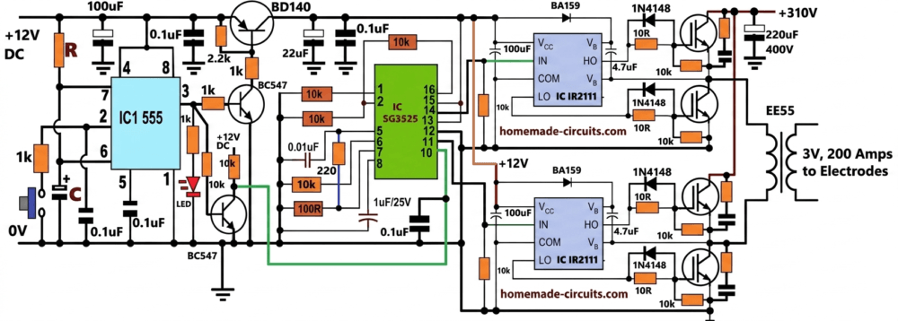
Now the circuit, it is split into parts. we have IC 555, then SG3525, then IR2111, and power side with IGBT full bridge and transformer, all working together step wise.
First our ubiquitous IC 555, we set it as monostable. So when you press button, then it gives one pulse, that pulse decides how long welding happens.
IC 555 Monostable Output Pulse Duration
Formula stays:
t = 1.1 * R * C
Let us take values, R = 18k, C = 1uF, so now:
t = 1.1 * 18000 * 0.000001
t = 1.1 * 0.018
t = 0.0198 seconds
So we get near 0.02 seconds, yep around 20 milliseconds, so now current flows only for that short time.
SG3525 Configuration
Then SG3525 comes in, which makes high frequency PWM, needed for transformer, without that nothing can work...
Its Output Frequency Formula is:
f = 1 / Ct(0.7Rt + 3Rd)
Values we take, Rt = 10k, Ct = 0.01uF = 0.00000001, Rd = 220 ohms.
So now step by step, but loose:
0.7 * Rt = 7000
3 * Rd = 660
Add them, 7000 + 660 = 7660
Now multiply with Ct:
0.00000001 * 7660 = 0.0000766
Then frequency:
f = 1 / 0.0000766
So it comes near 13054 Hz, which means around 13 kHz, that is the switching speed.
Now during that 20ms window, transformer does not see one pulse, it sees many alternate square wave pulses, which makes things smooth.
Formula:
cycles = time * frequency
So time = 0.02, frequency = 13000
cycles = 0.02 * 13000 = 260
So around 260 cycles happen in that small time, so energy goes nicely.
How the H-Bridge Stage Works
Now full bridge part, SG3525 gives two opposite signals, those go into IR2111 which then drives 4 IGBTs, arranged in full bridge.
So voltage flips like +310V then -310V across transformer, again and again, at that 13kHz speed, so now AC is formed at high frequency.
The ferrite transformer then steps things down, so that voltage is stepped down low, and current is stepped UP, and goes high.
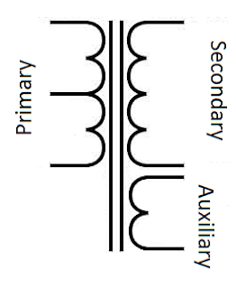
Calculating the Ferrite Transformer
First thing, we must clear this, that this is not a flyback type transformer, so it is not an energy storage type. Rather this SMPS welding transformer employs a full-bridge forward type topology, or an energy transfer type design. Meaning we cannot use the normal flyback type of calculations where duty cycle significantly decides the output voltage. We will learn more from the following calculations.
So we check power first, because everything starts from that.
Output is 3V and 200A, so power becomes
P = V * I
P = 3 * 200
P = 600W
Now since nothing is perfect, we assume efficiency, let us take η = 85%, so input power must increase.
Pin = P / η
Pin = 600 / 0.85
Pin ≈ 705W
So now we know roughly how much power is entering.
Next we check primary current, since input voltage is high.
Vin = 310V
Average current:
Ipri(avg) = Pin / Vin
Ipri = 705 / 310
Ipri ≈ 2.27A
Now switching current is not flat, so peak becomes higher, for square wave we take double.
Ipeak ≈ 2 * Iavg
Ipeak ≈ 4.5A
Now duty cycle, in our SG3525 usually does not go full, it stays near 45%, so we take:
D ≈ 0.45
Now here is the shift, since this is not flyback, we do not use energy storage formula E = (1/2) * L * I², instead we follow volt-second balance, which is what forward type uses, so now turns depend on that.
Primary turns formula:
Np = Vdc * D / (4 * f * Bmax * Ae)
Now we put values step by step, slowly.
Vdc = 310V
D = 0.45
f = 13kHz
Bmax = 0.2T
Ae = 2.5 cm²
First multiply top:
310 * 0.45 = 139.5
Now bottom:
4 * 13000 = 52000
52000 * 0.2 = 10400
10400 * 2.5e-4 = 2.6
So now:
Np = 139.5 / 2.6
Np ≈ 54 turns
Okay, primary becomes roughly 54 turns.
Now secondary, hmm, since voltage is very low but current is huge, we cannot just think ratio blindly, but still we start from ratio idea.
Ns / Np = Vout / Vin
So:
Ns = 54 * (3 / 310)
Ns ≈ 0.52 turns
That is not practical, so we take 1 turn, that is how it is done.
Now current side becomes serious, because 200A is not small.
We take current density:
J ≈ 10 A/mm²
So area:
A = I / J
A = 200 / 10
A = 20 mm²
But that is minimum, so better we go higher, like 30 to40 mm² copper strip, yep that looks safer.
Now primary wire, current is small there.
Primary current around 2.5A, so:
J ≈ 4 A/mm²
A = 2.5 / 4
A ≈ 0.6 mm²
But we do not go that tight, we use thicker, maybe 2 to 3 mm² multi-strand (litz), runs cooler, more stable.
Now check output voltage using duty cycle because here duty cycle directly controls output.
Vout ≈ (Vin * D * Ns) / Np
So:
Vout = (310 * 0.45 * 1) / 54
Vout ≈ 2.58V
So now we see, it falls inside 2 to 3V range, which is what welding needs, so it matches nicely.
So final build becomes like this:
Primary around 52 to 55 turns, multi-strand wire.
Secondary 1 turn, thick copper strip 30–40 mm².
Frequency near 13kHz
Duty cycle around 0.45
Importance of Deadtime
In real life, output at no load maybe 6V to 8V but when welding then it drops to 2V or 3V, but current shoots very high, like 200A or more.
Now that deadtime resistor of SG3525, Rd = 220Ω, it gives dead time, meaning when one switch turns off then other waits a bit, so no shoot-through.
If Rd is low then frequency goes higher and power also, but risk comes, if high then safe but less power, so 220Ω is kind of middle.
H-Bridge Output Stage
Power supply side, AC becomes 310V DC, then one 220uF / 400V capacitor smooths it, that cap handles heavy pulses....
Protection
Protection is also there, two levels, not fancy but useful.
One fast shutdown using SG3525 pin 10, and another hard cutoff using BD140 transistor, so if something goes wrong then system stops fast.
Overall Working
Now overall working, see, when button is pressed then 555 gives 20ms pulse. Then SG3525 starts oscillating near 13kHz, IR2111 drives IGBTs, full bridge feeds transformer, transformer sends high current to electrodes.
After 20ms, then everything stops. PWM stops and power also cuts, so weld happens in controlled burst.
Some practical things, keep transformer tight. Use thick copper for secondary, wiring short, heat sink on IGBTs must, and when testing first time then use low voltage, do not jump direct.
So to conclude, this SMPS spot welder is efficient, small in size, gives controlled pulses, and welding stays strong if built properly.


Questions & Answers
MANY TKS . PLEASE DON´T STOP
ENGº LUIZ ALVES
You are welcome Luiz…