A tachometer is a device that measures the RPM or angular velocity of a rotating body. It differs from speedometer and odometer as these devices deal with linear or tangential velocity of the body while tachometer a.k.a. “tach” deals with more fundamental the RPM.
Introduction
Tachometer is composed of a counter and a timer both of these working together provides the RPM.In our project we are going to do same, using our Arduino and some sensors we will setup both a counter and a timer and develop our handy and easy tach.
Prerequisites
Counter is nothing but a device or setup that can count any certain regular occurring event like passing of a dot in disc while in rotation. Initially the counters were built using the mechanical arrangement and linkages like gears, ratchets, springs etc.
But now we are using counter having more sophisticated and highly precise sensors and electronics.Timer is an electronic element that is able to measure the time interval between events or measure time.
In our Arduino Uno there are timers that not only keep track of time but also maintain some of the important functions of Arduino. In Uno we have 3 timers named Timer0, Timer1 and Timer2. These timers have following functions-• Timer0- For Uno functions like delay(), millis(), micros() or delaymicros().
• Timer1- For the working of servo library.
• Timer2- For functions like tone(), notone().
Along with these functions these 3 timers are also responsible for generating the PWM Output when analogWrite() command is used in the PMW designated pin.
Concept of Interrupts
In Arduino Uno a hidden tool is present which can give access to a whole lot of functioning to us known as Timer Interrupts.Interrupt is a set of events or instructions that are executed when called interrupting the current functioning of the device, i.e. no matter what codes your Uno was executing before but once an Interrupt is called Arduino execute the instruction mentioned in the Interrupt.
Now Interrupt can be called at certain condition defined by the user using an inbuilt Arduino Syntax.We will be using this Interrupt in our project that makes our tachometer more resolute as well as more precise than the other Tachometer project present around the web.
Components required for this Tachometer project using Arduino
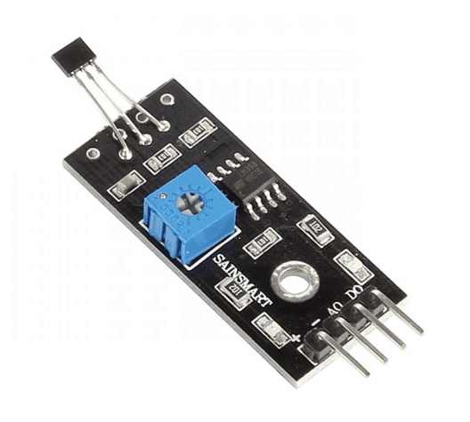
• Hall Effect Sensor (Fig.1)
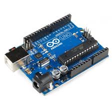
• Arduino Uno
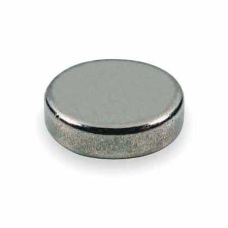
• Small magnet
• Jumper wires
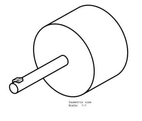
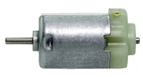
• Rotating Object (Motor shaft)
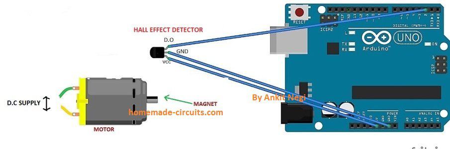
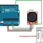
Circuit Setup
• The setup for creating is as follows-
• In the shaft whose rotation speed is to be measured is fitted with a small magnet using glue gun or electrical tape.
• Hall Effect sensor has a detector in front and 3 pins for connections.
• The Vcc and Gnd pins are connected to 5V and Gnd pin of Arduino respectively. The Output pin of the sensor is connected to the digital pin 2 of the Uno to provide the input signal.
• All components are fixed in a mount board and Hall detector is pointed out from the board.
Programming
int sensor = 2;                 // Hall sensor at pin 2
volatile byte counts = 0;       // Must be volatile (used in ISR)
unsigned int rpm = 0;           // RPM is always positive
unsigned long previousTime = 0;

void count_function()           // ISR
{
  counts++;                     // Increment pulse count
}

void setup()
{
  Serial.begin(9600);            // Initiates Serial communication
  pinMode(sensor, INPUT);

  previousTime = millis();       // Initialize timer
  attachInterrupt(digitalPinToInterrupt(sensor), count_function, RISING);
}

void loop()
{
  delay(1000);                   // Update RPM every second

  detachInterrupt(digitalPinToInterrupt(sensor));

  unsigned long currentTime = millis();
  unsigned long timeDiff = currentTime - previousTime;

  if (timeDiff > 0)              // Safety check
  {
    rpm = (60UL * 1000UL * counts) / timeDiff;
  }

  previousTime = currentTime;
  counts = 0;                    // Reset counter

  Serial.print("RPM = ");
  Serial.println(rpm);

  attachInterrupt(digitalPinToInterrupt(sensor), count_function, RISING);
}
Upload the code.
Know the code
Our tachometer uses Hall Effect Sensor; Hall Effect sensor is based on Hall effect named after its discoverer Edwin Hall.
Hall Effect is phenomenon of generation of voltage across a current carrying conductor when a magnetic field is introduced perpendicular to the flow of current. This voltage generated due this phenomenon help in Input signal generation.As mentioned Interrupt will be used in this project, to call Interrupt we have to setup some condition. Arduino Uno has 2 conditions for calling for Interrupts-
RISING- When used this, Interrupt are called every time when the Input signal goes from LOW to HIGH.
FALING-When used this, Interrupt are called when signal goes from HIGH to LOW.
We have used the RISING, what happens is that when the magnet placed in the shaft or rotating object come close to Hall detector Input signal is generated and Interrupt are called in, Interrupt initiates the Interrupt Service Routine(ISR) function, which include increment in the counts value and thus count takes place.
We have used the millis() function of Arduino and previoustime (variable) in correspondence to setup the timer.
The RPM thus is finally calculated using the mathematical relation-
RPM= Counts/Time taken Converting the milliseconds to minutes and rearrangement we gets to the formula= 60*1000/(millis() - previoustime)*counts.
The delay(1000) determines the time interval after which the value of RPM will be updated on the screen, you can adjust this delay according to your needs.
This value of RPM obtained can be further used to calculate the tangential velocity of the rotating object using the relation- v= (3.14*D*N)/60 m/s.
The value of RPM can also be used to calculate the distance travelled by a rotating wheel or disc.
Instead of printing values to Serial monitor this device can be made more useful by connecting a LCD display (16*2) and battery for better usage.

Comments
Sir
Can u give me a circuit
Which can auto cutt of When Volt below 4 v
i need this circuit for 9v rechargeable battery
Sharoj,
4V cannot be the lower threshold for a 9V batt, it should be 8V,
anyway you can try the second design from the following design:
https://www.homemade-circuits.com/2012/07/make-6v-4ah-automatic-battery-charger.html
Dear
please give me a circuit diagram That uninterup Dc power supply 9v volt.
battery 3.7 volt . Power supply 5v
if power supply gone then Power supply will be continue to my 9v modem by battery …
you can refer to the following design
https://www.homemade-circuits.com/2013/03/simple-dc-ups-circuit-for-modemrouter.html