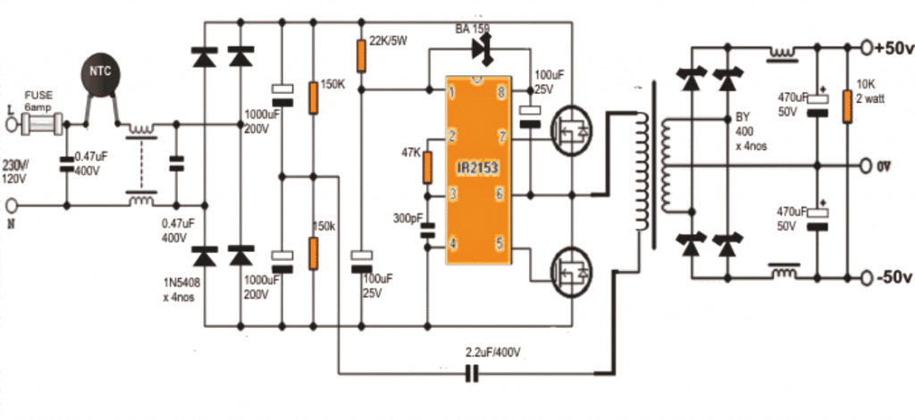
This article will illustrate a simple procedure to devise an unregulated 50V switching SMPS symmetric power supply of 350W. This unit can be substituted with the standard audio amplifier power supply to reduce expense and also the weight. The proposed power supply works as a half-bridge with no regulation.
Written and Submitted by: Dhrubajyoti Biswas
Mosfets as Power Devices
My power supply relies on two N MOSFET and run by IR2153 integrated circuit. The IR2153 is powered by a power resistor of 27K 6W. The ripple at full load is recorded below 2V.
The use of Zener diode (15V) ensures voltage stabilization and the operating frequency is set to 50 kHz (approx.).
At the point of the input, I have placed a thermistor to force a check on the peak current when the capacitor is getting charged.
This same phenomenon can be found in AT/ATX power supply unit of a computer. Moreover, to ensure low leakage inductance and full voltage output, the first half of the primary is wounded in 20 turns followed by the secondary wound.
Also to assure safety in the system, do be sure to connect the output (center tap 0V) to the earth.
Chokes for Filtering RF
The chokes used in the design will facilitate removal of RF output ripple. The number of turns and the core which is found in PC supply is not a critical factor.
Additionally, the 6k8 resistors at the output section is used to discharge capacitors after it is switched off and this way it helps to prevent the voltage increase during no load.
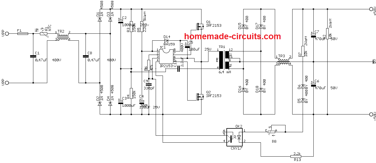
The proposed Switched power supply 2x 50V 350W operates in single switch forward topology. It has an operating frequency of 80-90 kHz and has IRF2153 control circuit which is very much similar to that of US3842. However, the duty cycle is lesser and is limited to 50%.
Rewinding an ATX Trafo
The Tr1 transformer was devised by rewinding the SMPS ATX transformer and its primary inductance is 6.4 mH (approx.).
The core of the system has no air gap and the primary inductance is further broken in two parts: The first half is the wind and the second is the winding.
Moreover, it is also feasible to deploy the original primary bottom half without rewinding. This type of power supply aptly suits for power amplifier applications.
If required it may be also safeguarded against overload or short circuit and the voltage of the output could be stabilized. The Feedback of the system may be enabled through the help of optocoupler.
It is important to note that in regard to 350W power, care should be taken that in the conductive state the typical resistance should not cross more than 0.8R. MOSFET can also be used to lower the point of resistance.
Interestingly, the smaller the resistance better is with the system.
The voltage tolerance is in the range of 900-1000V. In the worst case scenario 800V can be used. Considering this, the best MOSFET I found was SPP17N80C3 or 900V IGBTs.
Circuit Diagram
Coil Winding Details:
- The main SMPS transformer which can be seen integrated with the MOSFETs may be wound on a standard 90 by 140 square mm ferrite bobbin core assembly.
- The primary side winding consists of 40 turns of 0.6mm super enameled copper wire.
- Remember to stop after 20 turns, put an insulation layer with an insulation tape and wind the secondary winding, once the secondary is wound, insulate it again and continue with the remaining 20 turns over it.
- Meaning the secondary winding gets sandwiched between the primary 20 + 20 turns.
- The center tap of this 20+20 may be connected with the body of the SMPS for an improved stabilization and cleaner outputs in terms of ripples or buzzing interference.
- The secondary consists of a center tapped 14 x 2nos turns made by winding 0.6mm super enameled copper wire.
- The input and output filter coils may be wound on ferrite torroidal cores. The paired winding must be wound on the same individual torroidal cores using 0.6mm super enameled copper wire with 25 turns on each arm of the relevant supply terminals.
Update:
The above design 350 watt SMPS circuit was further improved by one of the dedicated members of this website Mr. Ike Mhlanga. The complete schematic of the same can be witnessed in the following figure:


Comments
Hello sir you were right the beginner can’t to the professionals work.
But still i have a question this circuit diagram can be also used for 24v 10a SMPS
?
Is that Voltage and amps are depends on the winding of the transformer ?
Hello John,
The above circuit can be used to produce 24 V 10 amp by suitably adjusting the secondary winding.
Voltage and current depends on the transformer winding, and the MOSFET rating.
And can we up and down the voltage in this circuit?
And nothing will change instead of windings and mosfets ? Everything will be same ?
That is correct.
Sir can you give me clear image i can’t see components name both pictures aren’t clear enough!
John, the image is quite clear, I can see all the numbers correctly, please let me know which part number you are not able to understand.
So sir it’s a 24v 15a SMPS design??
Yes it should produce 15 amp current, if the output winding is adjusted to 24V output.
As warned before if you are a newcomer and have no experience with SMPS circuits, you will probably fail to build this design successfully and in fact you might end up up burning something or meet a fatal accident.
I need 2x50v,350w power supply for audio amplifier.how I get this p/s
You can build the above explained circuit….
Thank you sir for ur assistance.I appreciate.
Thank you sir for responding so quickly.on the link you reffered me, what modification can b done to it for dual rail voltage?
For converting into dual voltage you will have to create a center tap across the secondary winding, and then add the rectifier, filter stages as done for the circuit in the above article.
Hi sir pls I wish to build a dual rail power supply just like this one to power an amplifier. Is it possible to build it with 3844 ic.if yes pls can u suggest me a circuit diagram?
I’ve seen in some home theater system
and DVD player that have just one MOSFET switching the primary winding of the transformer and the secondary side has dual supply to power operational amplifiers n I don’t know the kind of topology used.though I’m a learner.so I keep wondering if could build such kinda power supply but I really need guadiance on this.
I tried building this circuit but blew couple of those transistors which are quite expensive where I am.please sir I need ur assistance.
Hi Abubakar,
The above design is a tetsde one and it worked fine for many readers, I am not sure why you could not succeed with it.
You can try searching “Switched power supply 2x 35V 350W using IC 3844” you should be able to find the required design using 3844 IC.
I think I have a single mosfet based SMPS in this blog. You can refer to the following design:
https://www.homemade-circuits.com/12v-5-amp-transformerless-battery/
hi sir..i know you are profesional..i have aquestion::i want a powersuply like you desined but i need(+170volt and -170volt..with 1amper )))in out put what sould i do??please lead me and thanks
Hi Muhammad,
You can try increasing the number turns at the secondary side until you get the 170V output. This is my assumption I am not fully sure about this. But you can try this.
Do you have design of regulated Switch Mode Power Supply of 50V 300W or 50V less watt , but it needs to be regulated to 50V under varying maximum load condition 5A?
The regulated version of the first circuit is shown at the end of the article.
Is it a closed loop microcontroller based power supply?
Does the output voltage 50V remain constant under varying load condition of 0-7A?
Does the output voltage 50V ,changes with changing load current?
It is an SMPS based power supply but it does not have a feedback control, so the output voltage will not be constant 50 V.
But you easily add a opto coupler based feedback loop mto keep the output constant.
The transistor collector of the opto can e configured with pin#3 of the IC IR2153 for the required automatic voltage correction.
Actually this configuration is shown in the last diagram
Can we use transformer core on which number of windings of copper wire are made to form chopper?
Is the chopper used in switch mode power supplies same as the transformer core on which copper winding is done?
How do we determine, how many turns are to be made on primary side and on secondary side for design of 350W power supply?
Sorry, I could not understand your first question regarding chopper winding?
For the number of turns on an SMPS transformer you can use the following article for the calculations:
How to Calculate Ferrite Core Transformers
Do you have Proteus digram for this circuit?
Sorry, I do not have a Proteus diagram for this project
Need help in designing closed loop buck converter of 20A 50V
What turns of Switch Mode Power Supply transformer primary and secondary you keep.What diameter of copper wire you used?
Will our circuit run if we plug in the single phase from the bridge rectifier and no using input filters?
The turns will be the same as explained in the above article, but the thickness of the wire will need to be experimented. I think for a 20 amp transformer, the primary side will need to be built with 1.5 mm thick wires, and the secondary side with 2.5 mm thick wires. The circuit can be used without the filter also.
Hello sir!
if I want to increase the output, for example I want to increase the output of 12, 9 and 5 volts. do i just add a regulator ic to the output?
thanks sir
Hello Fernandy, you can add voltage regulators but they can too hot when a load is added, instead you can measure and extracts taps from the secondary winding appropriately corresponding to the 12, 9 and 5V.
Hi Swagatam, i built your amp design awhile ago and was very successful !!. I’m trying repair/modify a SMPS for an expensive power supply(to replace) ,it seems to be flyback design , i built a circuit based on IR2153 very similar to above design from application notes for IR2153, i’m only getting a pulse on pin 5 to drive mosfet, when i connected circuit to drive primary winding on SMPS the fet on pin 5 exploded, i isolated the transformer from driver circuit of damaged PSU completely, how can i make/modify this design to drive an unknown primary winding, by adjusting frequency until correct saturation is reached , should frequency be adjusted from low value to high value or vise versa, or …………..
Hi Andrew, SMPS are usually built with a lot of calculations, however you can try this quick remedy.
You can put a 40 watt AC bulb in series with the input AC, and then gradually adjust the frequency until you find the lamp shutting off completely.
Then with this set up you can add a load at the output of the SMPS and check if that proportionately causes the glow on the lamp to increase.
In this way the right matching frequency could be perhaps confirmed.
I have found this quite an interesting article, will have a little experiment!
One value I am not sure about (on the updated version from Mr Mhlanga) is for the Trim Potentionmeter R8? I am assuming it needs to be fairly large say 20K to keep it off and trim to just the right level at full current but I could have this wrong?
I am assuming that the 2.2uf capacitor needs to be 400V? albeit If I am thinking correctly this and the two 1000uf capacitors run at half rail so maybe 200 ish would be fine? I plan on using 400v throughout but for cost reasons this may be a reasonable approach.
(The 470uf Capacitor seems to be marked as 50v, that is probably better at 63v to give a bit of margin).
once again thanks not just for the article but your patient responses to all the posts.
Glad you liked the article, hope it works for you!
The R8 is actually wrongly placed. It should be placed in a resistive divider manner with reference to ground. In the indicated position it will do nothing except limiting the LED current, which is already limited by R7.
Yes the 2.2uF can be a 400V capacitor.
I would recommend using 400V for all the AC related capacitors, for ensuring extreme safety.
Yes the output 470uF capacitors must be rated at 63V or 100V for better safety.
Great thanks for the feedback, I am not sure this part of the circuit will work as defined even with that tweak, could just be myself not understanding the circuit, the rest looks fine. So I will experiment with the sense circuit before commiting to a board!
I will probably evaluate using a zener like in one of your other designs as that is something I am more used to using.
Sure, no problem, you can also experiment with TL431 instead of the zener diode
Dear Swagatam I am looking for a Schematic for 45-0-45 volts (2Amps) 0-12 volts 1amp and 5volts 1amp to drive a preamp if you could help me Thx. Peter
Swagatam Thx for that, Peter
Hi Peter, I don’t seem to have a transformer based 45-0-45 V power supply design. The SMPS version is shown in the above article. The 12V and 5 V could be probably derived by adding additional windings on the secondary side of the transformer.
Dear Swagatam,
Many thanks for your article. Can you send me a 24V-0-24V 2A SMPS circuit diagram?
Thanks
Thank you Hemantha, I think by proportionately reducing the secondary winding by 50%, an output of 24-0-24V could be achieved.
Sir, Kindly Said me +/_50v 350 Watt= How much in Ampere
How to manage 0.6 mm dia secondary wire to 7 amps?
Subrata, the current will be 350 / 50 = 7 amps
hi how can i replace IR2153 IC with 555 timer
You will need to replace the high side MOSFet with a P-channel MOSFET
Hello my friend my name is RIDDER JESUS CORDOBA I am an electronic technician in repairs and reconstruction of commercial fm transmitters in the 88mhz 108mhz range. field experience 40 years.
mirreto is to put together an adjustable switching power supply 2v to 50v 10 ampe.r
only elogrado 5 amps with ic ir2153 very good result in the stability of the output of the voltage 2v to 50v I wonder can you get 10 amps. I could work with voltage input 120vac or 220vac
what is the recommended tension
Thank you friend, I guess you are referring to the above SMPS design, so yes you can get 10 amps also from it by upgrading the wire thickness of the transformer appropriately, and by experimenting with the value of the 2.2uF/400V capacitor…
Dear Swagatam,
First I want to thank you for your site, thats great i get many ideas it.
Second I have a question that how can i use this power supply with this configuration as adjustable SMPS ?
Can I change the R8 in opto to potentiometer for changing the output put voltage for example from zero to plus/minus 50 volts ?
Best regards.
Dear Saeid, you can try implementing the steps as indicated in the last diagram of this article:
https://www.homemade-circuits.com/how-to-make-variable-current-smps/
Is it possible to protect mosfets with suitable varistor mount between drian and source?
Forgot to say that the mosfets i used in the circuit was 20A rated.
The NTC at the input side would be already doing this for the MOSFETs
Thanks bro,
But i did used a 5ohm NTC in other main line.
(5A fuse in one line and 5ohm NTC in other main input)
NTC should have worked, because its resistance is supposed to increase as its temperature increases due to an increase in current. You can try 10 Ohm NTC and see it that works.
Sorry, NTC will not work, since it will do just the opposite of what I have mentioned above.
Hi
I made this circuit and changed the winding details which produced 13.7v perfectly. I did not know about the ultimate current so i connect it to 10A load. It perfectly tolerates start up pluse current up to 18A in running dc motor without voltage drop. As result the 5A fuse and both mosfets blown. I want to know how can i limit current on such circuits. Did it work if i connect a low ohm resistor in series with lower mosfet?
Would you please refer me some of current limiter circuit or methods?
Hi, thanks for successfully building this circuit. For current limiting you can try applying a transistorized shut off stage as shown in the following diagram:
Hi,
I add bc547 with a 1ohm resistor to limit the output current but the transformer made noise like wiiizz. Is this ok or should i change somthing?
Hi, May be the BC547 is distorting the frequency of the IC, but that is the only place we can integrate the BJT for the shut down. If it is controlling the current then it should be OK.
Hi Swagatam,
Regard to the current limiter in form of BC547 and low resoistor, I have the issue of finding resistors for like for 10Amp due to the formula you said. I tried to reach desire value by adding series of them but it take too much resistor. Are there other ways like circuit current limiter or how to make such low resistor.
Hi Mah, the input side will not be 10 amps since it is working with 220 V. Please divide the wattage with 220V to get the input side current, and then calculate the limiting resistor according to this current value
Thanks, can i use this for selecting Mosfet current?
I mean selecting mosfets base of input side current? Or it must be base on output current?
MOSFET drain current should be two to three times more than this value, then it will be fine. Gate is not current dependent, it is voltage dependent.
Thank you so much for updated circuit.
Could you please guide me in selecting Rx value?
Is it ohm law?
No problem, you can try 0.6 / current limit, to get the value of Rx.
Hello Swag,
Between gate drivers ics which one is limited to 50% dutycycle and thier freqs. and dutycycle are controlable?
Hello Mah, the full bridge ICs whose output is controlled through their HIN and LIN input pins, by supplying external PWM, will allow you to get adjustable duty cycle.
Dear sir
what do you mean when you say 14 x 2nos turns?
It means 28 turns, with center tap taken out after the 14th turn
Thank you Swagatam!
Are those quantities calculated for a 110v input or a 220V input?
is 0.6mm enough for that power? (both primary and secondary)
How could I reduce the power to have 150W and + 35V -35V output?
Could I use 10 + 10 turns on the secondary to do it?
Could I use an EI3313 ferrite core?
Thanks Gabriel, the design is not mine therefore I cannot confirm the data, however 0.6 mm appears to be OK for the mentioned power output.
You can reduce voltage by reducing the number of turns. 10 + 10 turns looks fair enough to start with.
The E core/bobbin should be such which accommodates the turns optimally, not too spacious, not too crammed
Hello,
Sorry for asking too questions.
The EE core i recovered from old computer power supply, has circular shape in its middle leg with 95 sq.mm area.
Does it work for this circuit?
Thanks
Circular leg will also work, it won’t be an issue, but the gap between the e cores must be separated by a paper or cello tape insertion.
But the winding must correctly fit inside the e core. There should not be too much empty space or too crammed.
Hi
What are suitable voltage and current for the Mosfets in this circuit?
Can I use IRFP460 with Vds:500 and Ids:20Amps?
thanks
Hi, it must be ideally minimum 800 v rated, so 500 v may be risky.
Hello
I cant find the BY400 diode here. It is hard to find the exact datasheet. Would you, please introduce me an equivalent component.
Thanks
You can try this instead
https://www.vishay.com/docs/86003/by228.pdf
Do you know about differences between IRS2153 and IR2153? Are they same? Here i can only find the first one.
Im asking this because i dont know much about their important parameters to compare. I’d be thankful if you do it for me.
Thanks
You can find the answer in this document:
https://www.infineon.com/dgdl/Infineon-IRS2153D_and_IR2153_IR2153D_Comparison-AN-v01_00-EN.pdf?fileId=5546d462533600a4015355958ca11028
both are similar except the one capacitor reduction in the newer IRS model.
sir, i want to convert this circuit to 5v 100a .
can it be possible to do so by altering secondary winding or any part is to replace plz guide me.
.
Sajal, try only 3 turns on the secondary using 30 strands of 25 SWG wire in parallel, this is an approximate estimate, I am not sure about the exact number for 100 amps
Hello, how much voltage should be on optocupler pin 1,2. Optocupler vr not working at all. IR2153 pin 5,7 how much voltage will be there after run the circuit.
message for Shahadat Hossain
did you make a PCB for that project ?
If yes , can youplease share with us ???
Thanks in advance
Dear massimo, I did make a PCB for the project, but it is under experiment. I’m not success yet.I need to know and do more about the circuit. When i will success, hope i will provide it here. tnx
shahadat
Dear sir, how to add more separate output coil 15volt for preamp since this 50 0 50volt is for power amp i need to add separate turns for preamp side. Thanks a lot
Rabiu, you can add some turns by trial and error and modify its number to get the required 15 V auxiliary output
good day sir, how many ampere do we get on this 350w circuit.
thanks
BrianR
Hi Brian, 350/50 = 7 amps
Rất hay và tôi thích cái đều này
Hello Love your site. I’m very new at this and want to build this SMPS 2 x 50V 350W Circuit
Could you be a little more detailed on this part of the build I have never done this and would appreciate all the details you can provide.
Thanks Mick
Glad you liked my my site, however regarding the coil winding all the details are already provided in the article, please let me know what exactly you are unable to understand, I’ll try to elaborate it for you. That said, please remember that this project is strictly for experienced engineers, not for newcomers
Thanks, glad you liked it!
Good Day Sir,…
I need a smps circuit for a power amplifier with a capacity of 1000 watts that is equipped with overvoltage protection at the output section, can you help me solve this problem
Good day Achmat, sorry I do not have a 1000 watt SMPS circuit with me at this moment!
the circuit above can be increased to 500 watts ?
yes it is possible by appropriately increasing the current handling capacitor of the transformer and also by increasing the 2.2uF capacitor value.
I’m curious why you put the ntc on the high current side? Ntc’s are not cheap and the higher the current and lower ear the more expensive they get. You’ll loose precious input power with that configuration. If you use an ntc in a dc to dc step up converter you would put it in between either transfo and diodes or diodes and caps minimizing losses and saving the feta and diode from getting hit to hard when the unit first turns on. Or better yet just use a soft start circuit.
I put it there because normally NTCs are put in that position. I have checked many SMPS boards and have found the NTC positioned right at the input of the mains AC as shown in the diagram. Anyway, I’ll leave it to the readers to try your suggestions and let us know how it works. Thanks for the information.
sorry, can you explain in detail the components that need to be changed
You have to first complete the circuit exactly as given successfully, and then note the inductance values of the transformer. After this you can upgrade the winding with thicker wire and may be with a bigger ferrite/bobbin. The wire must not be a single thick wire rather many thinner strands of wires held together. This should allow higher current to eb delivered by the system.
Next, you can try increasing the 2.2 uF/400V capacitor for optimizing the response even further..
Good day sir,
I really need a 200A 12V SMPS. Much lighter than a transformer of 2400VA. It is for an HHO machine. I need to lower the mains voltage to 12V and have a great current. I was thinking if i can do that with this topology, only modifying the transistors, the thickness of the primary and secondary and the number of turns of the latter and the transformer’s core. What do you say?
Good day Razvan, I am sorry I do not have a 200A SMPS design at this moment, If I happen to find it in future i’ll surely update it in my website!
Dear Swagatam
thank you very much for your circuit, designed by you. i successfully completed that. i am working with a pcb design.
That’s amazing Shahadat, thanks for the feedback.
Would it be possible to upload a small video of the working circuit to your Google drive and provide the link to me.
Then I could post it in the article with your credentials in it.
Hello dear swagatam! Your posts are always innovative, educating and quite impressive. I am glad to be a follower of your electronic circuits blog. Thanks for this post.
However, I want to be cleared of certain misconceptions. I really need to know if ba159 could be replaced with UF4007, and BY400 with UF5408?
again, according to your statement, I quote “The center tap of this 20+20 may be connected with the body of the SMPS for an improved stabilization and cleaner outputs in terms of ripples or buzzing interferences.” won’t the connection of the center tap of the primary winding to the body of the SMPS case cause shocking?
And finally, I hope I can used PC817 instead of the optocoupler used in the modified version?
Thanks in anticipation of your dedicated time and response…
Ok. If I get your explanation it means that the center tap of the secondary be connected to the metal case right? if so, does it mean that the metal case will as well be connected to the GND? I am referring to your statement and I quote “Also to assure safety in the system, do be sure to connect the output (center tap 0V) to the earth.”
Thanks and sorry for bordering you. I just want to get everything right before I can carry on with practical design.
Thanks my great mentor.
Just one more clarification. looking at SMPS, the output is (+50) – 0 – (-50) and for conventional amplifier power supply, the 0V which is the center tap of the secondary is usally connected to the GND of the amplifier circuit. Now if I have to connect the same 0V to the body of the SMPS, it also implies connecting the body of the SMPS with the amplifier’s general GND right? If so, won’t it result in negative effect to the amplifier since most of the amplifier control outlets such as volume resistors, spectrum analyzers, DVD socket, speaker jack etc are also tightened to the amplifier body; whereas the amplifier body is also the SMPS body as they both house in one case?.
please help me for this one last clarification.
Thank you.
Thanks Kingsley, the body of the SMPS is also a ground, similar to the amplifier ground, so connecting them together will have no effect on the amps performance. Ground is a neutral line which is supposed to absorb all the negative noises and disturbances from the source.
Hello dear Swagatam!
Thanks for all the time you spent attending to my questions and uncertainties. Please I came across damper diodes (FMP-3FU and 5THZ52 and 5TUZ52) from an old store each rated at 5A, 1500V according to my research. But I really don’t get something about the damp stuff. So I want to Know if you have ideas of whether the damper diodes can be used as fast recovery diodes. according to what i saw during research both 5THZ52 and 5TUZ52 are similar in operation and both are, I quote as follows: “SILICON DIFFUSED TYPE (HORIZONTAL DEFLECTION OUTPUT FOR HIGH RESOLUTION DISPLAY, COLOR TV)”, while FMP-3FU is said to be DAMPER and it is said to be diode modulation for displays.
Please guide me about whether these diodes would be appropriate for the SMPS described here
Good day boss Swagatam! good to here from you again. For the suggestion, yes I used 470uf, 100v for filtering the output. And during testing, I also set the meter to high voltage DC reading.
Please I want to ask if the line filtering inductors are critical? I am asking this because I didn’t use them at all.
hope to here from you soon.
Cheers…
Thanks Kingsley, the inductors are only for cleaning spikes and noise from the output, it has nothing to do with the meter DC reading. I think you should check the output with an oscilloscope if you have one. or else you can buy a small one very cheaply from any online store, for just $20
Hello boss Swagatam, Please I have a bit misconception regarding the SMPS treated here. I have built this circuit but I noticed that my multimeter is unable to read the output DC voltage and I am very much sure that the voltage is there. Here are my encounters:
1. when I connect the SMPS to the mains, all things went well but when I tried measuring with a digital multimeter, no voltage was shown but the backlight of the multimeter lights ON.
2. When I tried bridging the output rectified voltage of the SMPS, it sparks showing that output voltage was flowing.
3. I tried using the output to power a filament bulb but found out it powers the bulb. This made me thought that the output was not rectified. But when I try using an AC voltmeter to check it , it doesn’t show anything either. That made me try switch the same filament bulb with my 24VDC batteries and found out that the batteries also could power the bulb and I came to conclusion that the output was actually rectified.
Now, I further want to ask does it mean that the output voltage DC of the SMPS when rectified with ultra fast switching diodes will keep the frequency high in the range of the SMPS switching frequency of 50Khz? If so, the what type of voltage meter should I use in checking the output VDC before connecting it to my target amplifier?
The switching Diodes that I used are 5THZ52 which I got from television panel.
The ferrite transformer I used is EI33 and I calculated the winding turns accurately.
All the other circuit components were used exact as it is in this circuit design no changes.
I hope to here from you soon boss!
cheers…
Hi Kingsley, did you connect the filter output capacitors? Also please make sure the meter is set at a higher DC range, may be 200 V DC range.
Ok, Thanks boss. I can now go ahead and try the circuit. I will detail my feedback to you later sir.
Thanks a lot
My pleasure Kingsley!
Hello Kingsley,
yes these are fast recovery diodes and can be used for SMPS applications, as far as I understand!
That’s right, connect the 0V secondary center tap with the body of the SMPS, and additionally connect the SMPS body with the mains earthing pin.
Hello Kingsley, thank you, glad you are liking my posts
BA159 and BY400 are high speed diodes. Please check the datasheet of the other diodes and check whether they are also high speed (fast recovery) diodes or not and having the similar current rating. If they the specs then definitely you can use them.
yes PC817 can e used.
the center tap of 20-0-20 is the secondary and isolated from the primary, so there’s no danger of any shock
Hlo sir i want to convert single rail supply 60-0 vdc to dual supply 30-0-30 vdc. How i cando it. Pls give me solution. Ask me on my email. Thnks
Hi Varinder, you will have to rewind the secondary winding of the transformer, and take out a center tap from the winding to get a 30-0-30 output
Dear Swagatam,
we have no ba159, can i use another diode? and can i use 11N120 IGBT?
Dear Shahadat, you can use other diodes like FR107, or any fast recovery diode…you can even try 1N4148
Good day sir,
Very nice schematic. Say i wonder if it will work with two FDL100N50F, an N-channel MOSFET that has 500V drain to source. I am asking because i see that in the schematic we have a connection 1st source-1st drain-2nd source-2nd drain.
Thanks Razvan, the IC is configured as a half bridge driver, so the MOSFET configuration is correct.
So will it work with two 500Vds mosfets?
yes, it should work!
Dear Swagatam,
I couldn’t find IRF2153, BY 400. What can use for those? can 4N25 be used instead of CNY17?
Thanks
Dear Hemantha, you can use any similar half bridge driver IC, you can search the term in Google “half bridge driver IC” you may find many alternative.
yes 4N25 is fine!
Dear Swagatam,
Many thanks for your article.
How to change it for 30V-0-30V and 24V-0-24V?
Does the secondary of transformer wind 14turns, tap and 14turns?
Please help.
Thanks
Thanks Dear Hemantha,
you can do it by reducing the number of secondary turns appropriately. Although this may require calculations, you can try doing it with some trial error.
The other method is to use a opto-coupler as shown in the last diagram and adjust the preset R8 accordingly.
Thanks dear Swagatam,
Can EE ferrite core of PC Power supply be used for main transformer?
Thanks
Hi Hemanta, you can try it but I cannot guarantee about its size. Make sure to connect a 100 watt bulb in series with the input to avoid accidental fire hazard.
Dear Swagatam,
When I search ferrite bobbin core, all types (E,RM,Toroid,U etc.) are shown.
What is the correct one? Can you show?
Thanks
Dear Hemantha, the core should be ideally EE type, like this:
https://www.homemade-circuits.com/wp-content/uploads/2019/06/e-core.png
Pak saya pengen blajar bagaimana merancang sirkuit elektronika,bagaimana menentukan nilai2 sebuah komponennya,selama ini hanya merakit kit separuh jadi.rasanya kurang puas kalau meniru rangkaian yg sudah jadi,kemana saya bsa belajar pak,mohon informasinya pak
Hi Zair, I appreciate your interest, however I have not yet created a tutorials for this, I may do it someday soon. Actually learning electronics is a dedicated long and slow process. You will have to first learn how small circuits work, like circuits using a single transistor or a few transistors, and then learn how logic ICs work, and then how special ICs like 4017, 4060, 4049, 4047 work. Once you start grasping their working then slowly you can combine them to create new customized circuits and in this way learn how to design your own circuits.
You can comment on desired pages I’ll try to solve your specific queries.
UC3842 có thay thế được cho ir2153 không as
UC3842 có thay thế cho ir2153 không as
có ic nào thay thế đươc ir2153 không as mình muốn thử nghiệm mà tìm không ra
Google cho “trình điều khiển IC nửa cầu với bộ dao động”, bạn sẽ có thể tìm thấy nhiều sản phẩm thay thế
sir–smps modification for +-22 v dc 350 w—-primary—turns –no of wires–gauge
secondary—turns –no of wires–gauge
also toroid coil specs
—-thank you
sorry rahul, I am not sure about all these details, it will need to be calculated as per the following article:
https://www.homemade-circuits.com/how-to-design-a-flyback-converter-comprehensive-tutorial/
Morning Sir. Really educative post. I would love you to write an article on SMPS, clearly differentiating the topologies Half bridge and Push pull, including their switching waveforms. These two have got me puzzled for a while, before I finally figured it. Also, clearly differentiate between a regular synchronous buck converter and the half bridge, in terms of their switching waveform.
Finally, could you also explain more about the feedback for this system, since w know the chip has no provision for feedback. What is the rationale behind using the shut down pin to achieve a regulated output?
Thanks a million for your answers, I read you blog daily, and its been most educating.
Thank you Mho, I had thought of presenting one such article by referring to the details from the following document
https://www.onsemi.com/pub/Collateral/SMPSRM-D.PDF
But I felt it lengthy and stopped the work due to lack of time, but in future I may consider introducing it in my website.
the shut down pin can be used for disabling the output as soon as an over-voltage is detected at the output, this situation will try to shut down the output which will cause an instant drop in the output voltage, which in turn will switch ON the circuit, and this cycle will keep repeating rapidly forcing the output to remain within the predetermined limits…
Ah…that is really clever. And how about under voltage? Typically when a power supply is loaded, the output tends to drop. How does this control method compensate for the voltage drop? Thanks.
Without IC two using MOSFET 36vdc 5a
Out put SMPS Circuit diagram
Thanks! for overload situations you can configure a current resistor/transistor stage with the shut down pin to get the same results. The current sensing configuration can be studied in the following article
https://www.homemade-circuits.com/simple-current-sensor-circuit-modules/
thank you once again. Can this topology be used for building lead acid battery chargers?
yes it can be used, just make sure to adjust the output voltage as per the battery’s full charge specs.
Swagatam ! Does it require modification in circuit too, if i don’t want to use center tap in secondary? Because, I don’t need dual output as my purpose is to get high current for welding. I’ll be increasing MOSFET’s and using thicker wires (maybe parallel twisted etc).
Second thing as i understood from the description you wrote. On primary side as there are 40T so i need to wind 20T create insulation then wind secondary turns and create insulation then finally wind back remaining 20T for priminary. Which means overall i need to keep secondary between the winding of primary.
Hi Edeson, You can use the same circuit which is explained in the above article, and only modify the winding with higher current wires…the winding method will be also the same, the wires could be upgraded by using bifilar system where many thinner wires are used together to make the winding capable of handling more power.
and yes the secondary center tap can be removed and modified into a single winding
however please note that whatever I am saying it is with an assumption, so please proceed with the necessary cautions.
Have you pcb ?
sorry PCB design is not available
hello sir .pls tell me how to select a capacitor value in a circuit while designing .
which capacitor?
Hai sir , I follow your site regularly its very good . i want to design 3amps/65v output smps . Its very urgent please help me .
Thanks for your replay i need only +50v not -50v .what changes should i do . need to change transformer windings or anything
.pls explain me
if you remove the center tap then the negative voltage side will go…..the secondary winding turns can be decreased to get a lower value at the output
Thanks Pavan,
you can try the concept explained above and modify its parameters to achieve the required output as per your specs.
hai i want to design 0-65v /3amps smps circuit .please help me
Dear Swagatam!
You wrote that the center tap of the primary coil should be tied to the body. Directly or through a series capacitor? The wiring diagram is not marked. I have not seen such a solution yet in other circuits, and it is strange to me that the high-voltage coil is directly connected to the body, which, in any case, acts as a protective ground. Is not the secondary side’s gnd bound to the body? I’m confused!
The value of the potentiometer in the second drawing is not indicated. How much is its resistance? The two mosfets can be IRF840?
Thank You for Your help!
Dear Zollee, the article was written by another author, and may be the secondary ws referred to as the primary, because the primary does not have any center tap.
the secondary is completely isolated from the primary therefore the center tap can be connected with the body to increase stability and reduce noise.
the value of the pot can be selected with the some trial and error or by referring to other similar SMPS designs.
Dear Swagatam,
Very nice circuits. Is the circuits already been tested?
Can i use the Ei33 core? do i need to used gapped or ungapped core.?
And what is the size of the wire? can i use a litz wire here?
Thanks to your blog is very helpful to our newbie..
Regards,
odie
Thanks odie,
yes it is a fully tested circuit, the size of the wire is given in the article under the winding details, it is 0.6mm for both the sides, the wire should be a super enameled copper wire. yes you can use a EI33 core just make sure the winding perfectly accommodates within the bobbin….the core surfaces in contact with each other must be separated with a paper gap.
sir,, i would like to build this,, maybe you have a pcb deign for this,, tnx a lot.
sorry reynaldo, I do not have a PCB design at the moment for this…
Sir, can I use 555 timer for pen generator and ir2111 for driving section????
Prince, No that won't be possible because 555 is not designed as a half bridge driver.
DearSwagatam,
hank you for the pearls of wisdom. I have seen another scheme which has a BC457 transistor tied to pin 3. It however is not simple. I will mess around with what you have suggested. I would however like to send you ms Eagle schematic for corrections. How do I do that??
Dear Ike, you can send it to
homemadecircuits @ gmail.com
Dear Swagatam,
Thank you for the feed back. I will try to implement using feedback via optocoupler. Its a more elegant way of implementing the control and self adjust to demand.
I have researched the net esp on edaboard.com and it seems the IR 2153 has no pin for voltage regulation but one for shut down ie pin 3. Could you suggesta schematic for implementing voltage control Mr Swagatam?? Thanx in advance for the help.
Thank you Ike, The shut down pin#3 itself can be used for the intended regulation, you can configure the optocoupler quite as shown in the following smps design,, or any other similar design
https://www.homemade-circuits.com/2014/02/220v-smps-cell-phone-charger-circuit.html
for your application the collector of the opto transistor could be integrated with the pin#3 of the IR2153
PRINCE JOSE>
THANK YOU FOR YOU REPLY…..
I HAVE SOME MORE DOUBTS CAN YOU CLEAR THAT…
>WHAT IS THE VALUE OF 'NTC'???
>HOW I CAN CHANGE THE CIRCUIT BRIDGED??
>OR CAN I ADD EXTRA TRANSISTORS IN PARALLEL??
>CAN YOU SUGGEST ANOTHER RECTIFIER DIODE FOR OUTPUT SECTION….
Dear Ike, you can use the same configuration which is discussed in the article, for the 16V you can drop the output either using an optocoupler based feedback loop or a LM338 dual power supply as shown below
https://www.homemade-circuits.com/2015/07/dual-power-supply-3v5v6v9v1215v-with.html
Dear Swagatam,
I would like to use the above SMPS to power my mixer. The output would have to be +16V 0 -16V and 48V for phantom power. Could you suggest the output configuration of the output transformer in this case.
Thank you in advance.
Ike
The NTC value could be 5 ohm, 11mm diameter, as shown in the following article:
https://www.homemade-circuits.com/2013/02/using-ntc-resistor-as-surge-suppressor.html
you cannot change anything in the design, it has to be exactly as shown.
more no. of transistors won't be required if you select the two mosfets with adequate rating.
you can use any 6 amp fast recovery diodes at the output
Hello Swagatam,
My name is Prince Jose… This is a nice diagram. I want +/-90v 8A, how i can make it with you diagram, and also can i change the winding wire thickness…..
Thank you Prince,
you can certainly achieve it by tweaking the secondary winding of the transformer….the current can be increased by using more number of parallel wires across both sides
Hello Swagatam,
I'm new here and I'm not sure if you have already posted the circuit that I'm looking for. I need a power supply/inverter/smps with 12VDC input (from car battery) with an output of +50VDC & -50VDC at least 10ampere current capacity or more. Much better if the circuit is configured in SMPS.
Thank you and more power to you….
Hi Roberto, you can try the above explained concept with some modifications.
Instead of the mains you can apply 12V to the left hand side circuit…and you will need to modify the primary/secondary winding of the transformer.
For the primary side you could try around 5 turns and for the secondary 20 + 20 turns
the turn ratio might require further analysis and modifications, since it's not calculated by me precisely
Instead of IRFP460 can I use IRFP260N?
please check their I and V specifications, if they match then you can interchange the two.
Hi!
I thought of doing so circuit (with these components):
substituting:
the first capacitors 0.470uF (400V) with 0.100uF (400V)
1000uF capacitors (200V) with 470uF (200V)
The 2.2uF capacitor (400V) with 0.5 uF (400V)
Potrebe work?
To me I need a single output of 50V 3-4A and no more than 200W.
You can do with these changes?
THANK YOU!
It should be exactly as shown in the diagram, other values could produce inefficient results
Hi!
I have a question about the two capacitors of 1000uF (200V). Can I use two 470uF (200V) instead of two 1000uF (200V)?
it will need to be calculated, most probably it may be possible to get 4A
With two 470uF I can get 4A?
lower value will reduce the current at the output….the value of these caps determines the output current
I appreciate your interest, however I am sorry, that would be difficult at the moment due to lack of time!
Dear Swagatam, I would like to build a regulated smps for my audio amplifier which will be capable of around 400 watts, and having a voltage of 50-0-50. If possible using the TL494 or similar device. I have quite a few ATX power supplies at hand and can salvage parts from them.
Thanks in advance
yes I understood, actually you can configure the supply pins of the TL494 in the similar way to the above shown design. that is connect the positive pin of the TL494 just as pin#1 of the IR2153 is configured…this might just work
Sorry for misleading you I was referring to a mains operated power supply.
Dear Silvio, you can try the following inverter design, just replace its trafo with the a ferrite trafo which is discussed in the above article for obtaining the intended results:
https://www.homemade-circuits.com/2014/06/smps-2-x-50v-350w-circuit-for-audio.html
thx 4 your adwise..i will try n post result.
hy,,,swagatam..u r genius
can i use troidal core ring.?? plzz give me ring size.
thx in advance..
Hi Nitin, a torroidal core will work, but might require an entirely different winding data which I am not sure how to calculate….you can try it and find the most optimal results with some experimentation.
Hi Swagatam…
In my Country, IR2153 IC is still rare. Because IR2153 IC is for a PWM Generator, can i change the IC to LM555 or CD4047?
Hi Naufan,
LM555 or CD4047 will not work, because these are not equipped with high-side drivers…..these are just ordinary oscillators, while IR2153 is a specialized half-bridge driver IC…
Thanks for this sir, though i saw it several days ago;the reason why i did't consider it much is all about the IC, i think i will a serious problem to find it in my local shop here in Tanzania, is there any other way around without involving ic?
Thanks though sir, thanks
Raymonds, unfortunately there's no easy alternative to the above IC because it's a specialized half bridge driver IC…and does not depend on a center tap trafo, rather uses a two wire trafo for an efficient performance.
Sir,do you have a layout for this schematic sir?
sorry, no PCB layout for this…
please boss i need your help now, i want you show me how to build power inverter, if you teach i will be happy for you?
you can go through the following article, it has most of the info regarding the subject:
https://www.homemade-circuits.com/2013/03/how-to-design-inverter-basic-circuit.html
Sir,
What will be effect on system ( Panasonic amplifier 7.1) if we give 50hz instead of 60 hz. Power supply is smps based.
2. The source of mosfet be given 110volt .but how can I get 110 volts .
Please help me
Hi Style,
frequency change will not make any difference to an SMPs, for getting 110v you can eliminate the center tap of the above circuit and acquire the required 110 V from it.
Sir I have one system which is operational on 110volt 60 hz.. What can I do to make its operational,as we have 220V 50hz.. Help me sir
Style, in the previous link of a VFD circuit, you can adjust and set the output to 120V 60 Hz or to any desired level as per the load specs, therefore according to me it would be suitable for your application too.
the power is related to the mosfets which can be upgraded as per the requirements.
Sir, System is 120 Volt and 60 hz. Can it be operated with 120 volt 50hz. The system power supply is smps based . does it effect the systems any way. And Sir , power rating is 500 watts. Can I use this give circuit for this.
Thanks n regard
you may have to buy a VFD or build yourself one as given here:
https://www.homemade-circuits.com/2013/09/single-phase-variable-frequency-drive.html
Dear sir.. what is the size of ferrite core…
a 15mm EE core should do the job, the size actually does not matter as long as it accommodates the winding comfortably.
hello sir,instead of ferrite core can I use iron core which is used in transformer ?
hello Rahul, iron core will not do, it has to be strictly ferrite
What if I use a ferrite EDT49, whether the number of turns on the primary and secondary side as you say?
And if the switching frequency is 90kHz, if there is a change in the circuit or component changes?
you can use any EE core as long as it accommodates the winding comfortably it'll be fine.
you'll have tweak and adjust the 47k/300pf values for getting the desired frequency with some trial and error.
Dear Sir
For making PCB what specification i have to tell to shop . i want to make 1000 watt stereo
I want good quality COPPER BOARD
Regards
Dear style today all standard PCBs are made on glass epoxy base, so presently it's the best both quality wise and cost wise.
Dear sir
What is the primary frequency because one place its mentioned 50khz and in another place 80- 90 kHz
Second thing what is the primary current to the transformer
Thanks and Regards
Dear style, it doesn't make much of a difference whether it's 50 khz or 80 khz, for precise answers you can calculate it yourself by referring to the IC datasheet and by inserting the 47k and 300pF in the given formula
Dear sir ,
Sir I want power supply 50-0-50. /12 amps. Wat would be the gauge of secondary coil and number of turn
Thanks and regards
Thanks a lot sir..
You have any topic related to transformer making . I mean to say like calculation of E and I core calculations, bobbins size calculation, what size of gauge wire to be use. So that I can make a different voltage and wattage of transformers.
Thanks and regards
style, presently I do not have all the info regarding ferrite transformer designing, once I collect it will surely update them in this blog…
Sir,
Above circuit can be use for audio Amplifier which u have given . in this article the difficult part is transformer. Is it possible for you give a separate topic on this with picture
Thanks and regards
Sir. i am open ferrite transformer from damage computer smps. its core size aprox 7.5mm X 10.5mm(aprox 79 square mm) can i use this? plz. reply. thank you
Koushik, you can try it, if the winding fits inside the core optimally then you can assume it to be fine and the circuit might work.
Dear Chinmoy,
yes the article is a rephrased version and may have a few errors since it was written by a person with only general electronic knowledge.
the circuit actually has nothing complex in it.
the IC is a half bridge IC which generates a push pull output for the connected mosfets, which in turn switch in a full-bridge manner due to the involved dual AC input configuration.
this results in an efficient induction across the output winding
if you can go through the datasheet of the IC, you'll be able to get a better picture of its functioning details
Dear Swagatam,
I would like to sympathize with style for his difficulties in understanding the transformer winding details. Though the idea behind this article is very innovative and commendable, the narration is very sloppy and written in poor English with a lot of grammatical errors. I am not criticizing your post, but I suggest a more detailed proof reading of technical articles for a better presentation. For an experienced hand it is okay, but for a less initiated person or a novice, it can be very confusing. A few drawings or pictures would have made a lot of difference, as suggested by style.
I congratulate you on the excellent articles you have written in your blog, keep it up.
Regards
style, there's nothing difficult in it if you read and follow the instructions carefully, if you have problems you can always ask me for further help….
Dear sir. which comp used optocoupler pin1(r8). and how to regulate output voltage? plz. explain. thank you.
Hello Kaushik, I would recommend you to first build the shown basic design successfully and then afterwards we can proceed with the optocoupler feedback.
sir can i use 20n60 replace of SPP17N80C3? plz. reply
Yes you can use it.
sir which number mosfet used its?
Koushik, It is given in the article, just above the diagram.