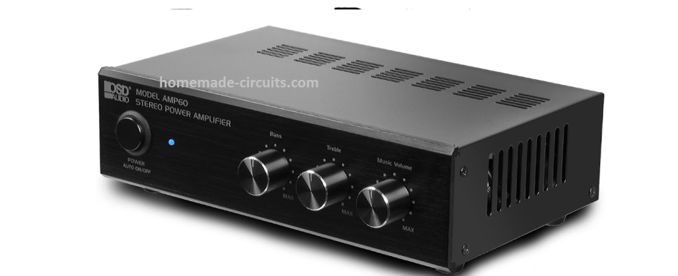
A complete, self-contained, small and compact Hi-Fi stereo amplifier circuit with bass, treble, volume control is presented in the following article.
This small compact stereo amplifier can be used for amplifying music from mobile phones, computer USB, Ipod or any source capable of producing as low as 50 millivolt signal.
Due to the high bass and high treble control facility, a pair small subwoofers can be used for getting an enhanced Hi-Fi music response from any ordinary music input.
Bass Treble Circuit
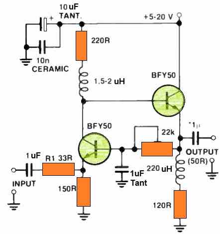
We will begin with a high gain, high fidelity bass treble controller circuit which forms the first stage of this compact table amplifier design.
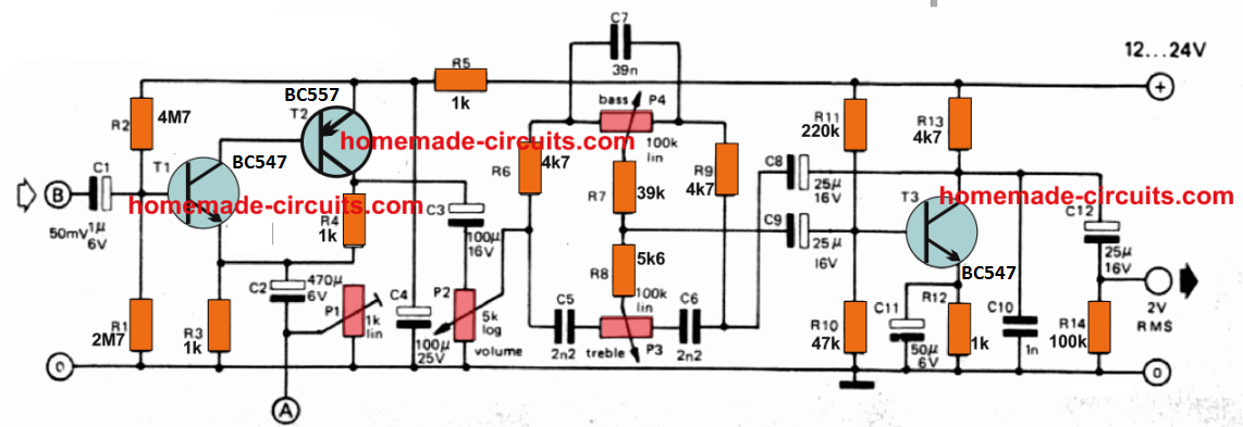
Transistors T1 and T2 are designed to function like a high input impedance voltage amplifier and with a low output impedance.
When the central slider arm of the preset P1 is adjusted to its full 1 k limit, the input sensitivity along with the small 5 watt amplifier gets to around 150 mV for the 12 -volt version, and when a 4 ohm speaker is used as the load. This may become 200 mV if the supply voltage is increased to 17 V and the speaker is of 8 ohm value.
If you need a greater input sensitivity, you can use the preset P1 value lower than 1 K. If you are interested to include a selective range for the input sensitivity, in that case you can put a selector switch with different resistors at the input for selecting the desired input sensitivity range.
The formula for calculating the resistor values is shown below:
Rx = 500 x Vin / 300 - Vin
where Vin depicts the input RMS value of the voltage in mV. The formula can be effectively used for all input voltages ranging from 5 mV to 250 mV.
The transistors T3 is configured as a Baxandall tone control circuit. The 1 nF capacitor between T3 collector and ground line is included to improve stabilization and restrict oscillations.
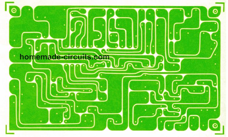
PCB Design for the Bass Treble Control Board
Compact 5 Watt Stereo Amplifier
The above explained active high gain tone control can be integrated with a personal small compact amplifier, as described below. This a tiny 5 watt version.
The output from the bass treble module has to be integrated with the input of the following amplifier circuit.
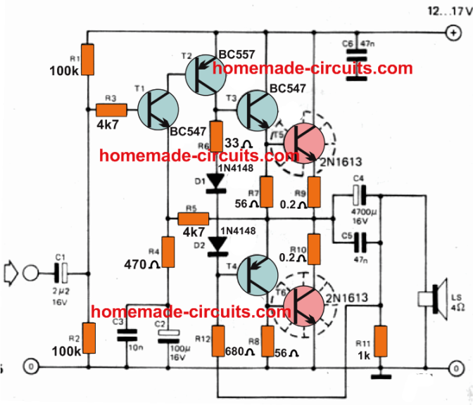
How it Works
Transistors TI and T2 is configured to work like a direct coupled voltage amplifier. Resistor R6 and diodes DI/D2 decide the level of idle current or the quiescent current consumption of the quasi-complementary driver stage T3/T4 along with the output stage T5/T6.
The resistors R7 and R8 values are selected in a way that the output transistors are either barely biased ON or just cut off. This is in turn determined by the the gain of the transistors used.
C3, C5, C6 and R3 are included to ensure proper stability of the design. The input sensitivity of this 5 watt amplifier is approximately 400 mV when a 12 -volt supply input and a 4 Ohm speaker is used load, and it is 600 mV when the supply is 17 V and the speaker resistance is 8 Ohms.
It is possible to improve the gain of the amplifier by reducing R4 but this may not be a good idea, since this may lead to instability and higher distortion levels.
The following care must be maintained for the design layout while installing the amplifier board inside the chassis.
- The negative wire of the loudspeaker should be connected directly with the main ground of the power supply and not to the amplifier PCB. This cable must be kept aloof from the circuit board.
- Each of the supply cables shown in the diagram must run separately to the board over the specified locations.
- The output section and the wiring of the board must be well isolated and kept away from the input wiring and stages of the board.
- To avoid earth loops, each and every supply wire must be individually connected and separately wired to the power supply from the board.
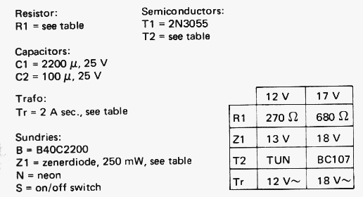
Parts List
Resistors:
- R1, R2 =100 k
- R3, R5= 4k7
- R4 = 470 Ohms
- R6 = 33 Ohms
- R7, R8 =5611
- R9, R10 = 0.2 Ohms
- R11 =1 k
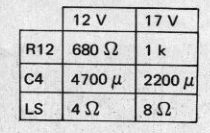
- R12 = see table
Capacitors:
- C1 = 2,2 µ, 16 V
- C2 - 10011. 16 V
- C3= 10n
- C4= see table
- C5,C6 = 47 n
Semiconductors:
- T1,T3 - Any NPN small signal general purpose
- T2,T4 = Any PNP small signal general purpose
- TS,T6= 2N1613
- D1,D2 = 1N4148
- heatsinks for TO -5
R12, C4 Selection Table
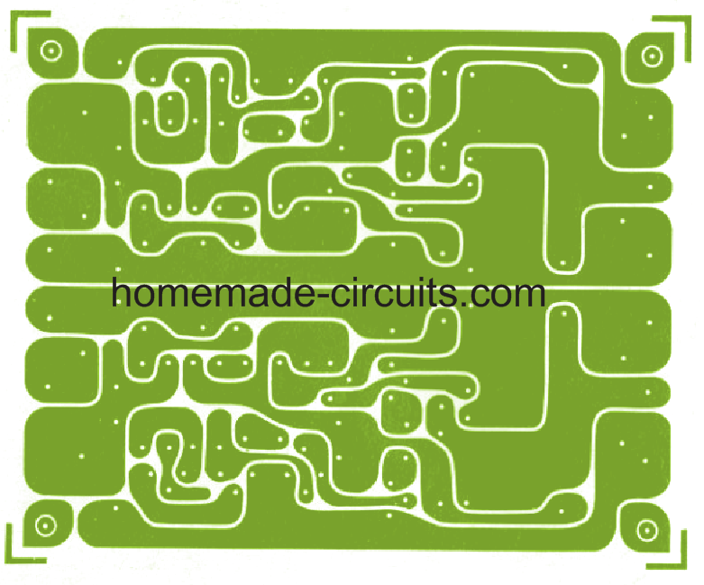
Stereo PCB Design
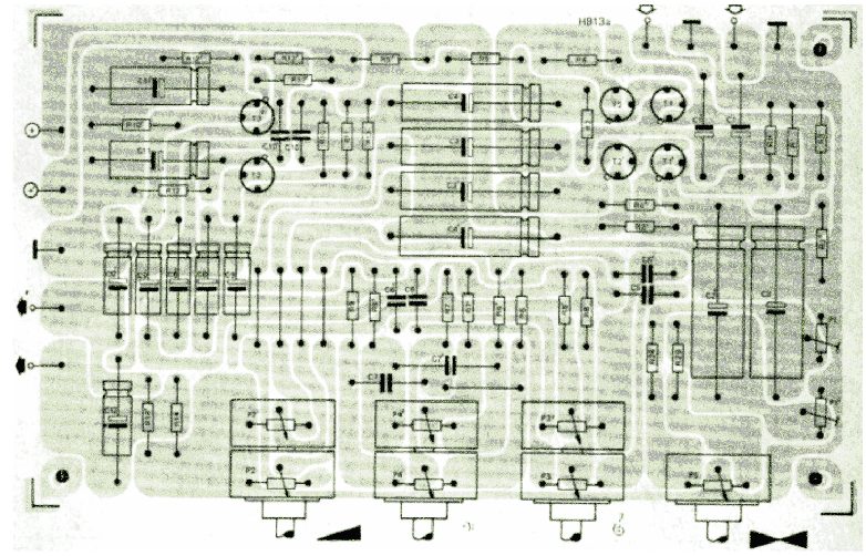
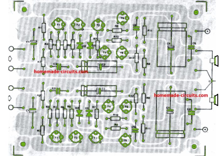
Component track layout for the above stereo compact PCB
Power Supply Circuit
The following diagram demonstrates the regulated power supply circuit for the compact stereo amplifier circuit.
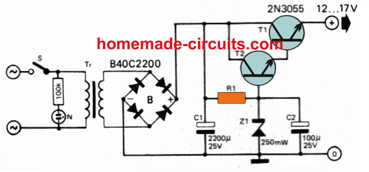
Transistors TI and 12 are wired as a Darlington pair so that it works like a composite high gain, high power emitter follower transistor.
The base reference voltage for this emitter follower is fixed through Z1 which may be selected as a 13 V or 18 volt zener for getting a 12 V or 17 volt supply respectively.
Due to lower input output differential T2 is supposed to dissipate very little amount of power as heat and therefore a heatsink may not be essential.
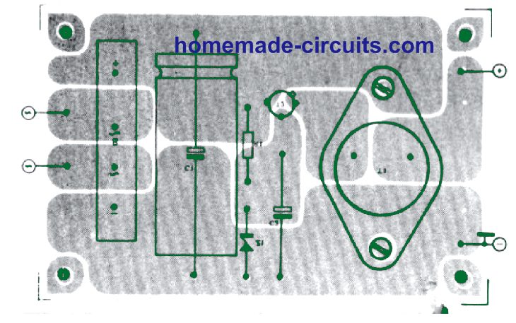
PCB Design and Component Layout for the Power Supply
The complete PCB layout for the power supply is given below:

Parts List


Comments
Excellent looking design; and old school hand-drawn PCB layouts (reminds me of the early 80’s, lol). I may do a video testing the power amplifier and preamplifier.
Dear Swagatam jee, in your power supply circuit you wrote T2 for 12 volt in table TUN, i cannot understand the meaning.
Hello Bijay, T2 can be any Transistor Universal NPN (TUN) such as BC547, 2N2222, BC548 etc.
Hello Swagatam,
Thanks for your kind speedy response and really appreciate it. Your reply clears my doubt. If this circuit works well then i’ve plans to built it for my workstation MP3 player.
Once again, thanks very much and have an excellent day.
Suresh/mal
You are welcome Suresh!
Hello Swagatam,
Greetings and hope you’re doing well. I’ve read some of your articles in your previous posts and they’re very helpful and informative to hobbyist like me too. Thanks for sharing this article on the mini stereo amplifier. However, i’ve a question. Looking at the bass treble control circuit, if point “B” is the input which is obvious, then what is point “A” which is below C2 and P1? Is “A” to be connected to the other channel circuit at the same point “A” too for balance control? Looking at the PCB layout, after C2, it goes to a resistor then to one side of the balance control potentiometer. Hope you could explain on this.
Thanks and best regards,
Suresh.
Thank you Suresh, it seems I forgot to show the connections for the point A. Yes you are absolutely right, it is to be extended for the balance control pot, as indicated in the following diagram:
Thank you Clifford, I’ll post the a 30 watt stereo amplifier article soon and let a know.
Sir, good day!
That would be great! I also emailed you on using the 2 emails provided on the website’s contact page
Thanks Clifford, I have understood your request and published the required articles in the below given link:
https://www.homemade-circuits.com/40-watt-amplifier-circuits-using-transistors/
Sir swagatam,do you have a simple schematic of how to advance any hi-fi amplifier say using LA4508 to a subwoofer? I would appreciate if so.
Evans, you can use a low pass filter between the audio source and the amplifier input.