There are many types of voltage-to-current and current-to-voltage converter circuits, and most of them use a combination of opamps and transistors to achieve a high level of accuracy. But when high accuracy isn’t necessary, a simple converter of this type can be made using just one or two resistors.
Resistor as Voltage to Current Converter
Any resistor R that is connected across a power supply V can be considered a voltage to current converter, since the current depends on the voltage via Ohm's law - the formula for which is I = V / R.
If one end of the resistor is disconnected, and another component D is connected to the disconnected power supply terminal and resistor so that R and D are in series across the power supply, the circuit still behaves like a voltage to current converter if the voltage drop across the component D is very small or relatively constant.
This component could be a diode, LED, or zener diode, or even a low-value resistor. The diagram below shows these possible combinations. The resistor R can also be thought of as a current limiting resistor for the added component D.
The current that flows through D is determined by the simple formula: I = (V – VD) / R, where VD is the voltage drop across the added component.
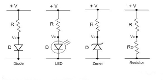
For constant values of VD and R, the current only depends on V. For forward biased diodes, VD is about 0.3 - 0.35 volts for germanium, and 0.6 - 0.7 volts for silicon diodes, and is relatively constant over a wide range of currents. LEDs are similar to diodes, except that they are constructed using special materials that emit light.
How LEDs Work with Resistors
They have a forward bias voltage that is a little higher than regular diodes, and could be anywhere from about 1.4 volts to over 3 volts, depending on the color. LEDs operate efficiently at about 10 mA to 40 mA, and a current limiting resistor is almost always connected to one of the LED terminals to prevent any damage due to high current.
There are slight changes in the voltage drops of diodes and LEDs for different current levels, but these can usually be neglected in the calculation. Zener diodes are different in that they are connected with reverse bias.
This sets a fixed voltage drop VD across the zener diode that could be anywhere from 2V to around 300V, depending on type. In order for any of these devices to work, the supply voltage has to be higher than the voltage drop VD.
Any value of resistor would work, as long as its value is low enough to allow sufficient current to flow, while at the same time being high enough to keep excess current from flowing. Usually there is a switching component inserted somewhere in this series circuit, which turns an LED on or off, etc. This could be a transistor, FET, or the output stage of an opamp.
LED and Resistor in Flashlights
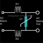
An LED flashlight basically consists of a battery, switch, LED, and current limiting resistor all connected in series. Sometimes, the current limiting circuit consists of two resistors in series across a power supply, instead of a resistor-and-diode type device.
The second resistor RD has a much smaller value than the current limiting resistor, R, and is often called a "shunt" or “sense” resistor.
The circuit can still be thought of as a voltage to current converter, as the above formula can now be reduced to I = V / R, since VD is negligible compared to V.
The current will now only depend on the voltage, since R is constant. This kind of circuit can often be found in various sensor circuits, such as temperature and pressure sensors, where a defined amount of current is to flow in a device with a small resistance.
The voltage across this device is usually amplified to measure any change as the sensor resistance changes under varying conditions. This voltage can even be read by a multimeter if it has sufficient sensitivity.
If the formula I = V / R is flipped around to become a voltage function V = I R, the simple two-resistor series circuit can be thought of as a current to voltage converter as well.
The current limiting resistor still has a value much higher than the sense resistor, and this sense resistor small enough that it doesn’t affect the operation of the circuit in any meaningful way.
Using a Current Sensing Resistor
A current is converted to a voltage by the fact that that the small voltage VD across the sense resistor can be detected by a multimeter, or it can be amplified and applied as a signal into an A/D converter.
This measured voltage indicates the current flow with the Ohm’s law formula V = I R. For example, if 0.001 A flows through 1 ohm, the voltage reading is 0.001 V.
The conversion is simple for a 1 ohm resistor, but if this value is too high, another value - like 0.01 ohms - can be used, and the voltage could easily be found using V = I R.
The actual value of the sense resistor is not important in this discussion. It can be anywhere from 0.1 ohms to 10 ohms, as long as the current limiting resistor is much higher. In high-current applications, the value of the sense resistor should be very low in order to prevent excess power dissipation.
Even with a value around 0.001 ohms, a reasonable voltage can be sensed across it because of the high current flow. In cases like this the sense resistor is normally called a “shunt” resistor.
This kind of circuit is often used to measure the current though a DC motor, for example. It is a simple matter to use a multimeter to measure AC or DC voltage at any point in an electronic circuit, such as on a PC motherboard. An appropriate voltage scale is set on the multimeter, the black probe connected to a ground point, and the red probe connected to the check point.
The voltage is then read directly. Hopefully the impedance of the probe input circuitry is high enough that it doesn’t affect the circuit’s operation in any way. The probe input impedance should have a very high series resistance along with a very low shunt capacitance.
Measuring Current Voltage in Complex Circuits
Measuring AC or DC current at any point in a circuit instead of voltage becomes a little more tricky, and the circuit might have to be modified a little to accommodate this. It might be possible to cut the wiring of a circuit at the point where measurement of the current flow is desired, and then insert a sense resistor with a low value at the two contact points.
Again, this resistor's value should be low enough that it doesn’t affect the operation of the circuit. The multimeter probes can then be connected across this sense resistor using the appropriate voltage scale, and the resistor voltage would be displayed.
This can be converted to the current flowing through the test point by dividing by the sense resistor value, as in the formula I = V / R.
In some cases, the sense resistor can be kept in the circuit permanently if the current at a particular test point needs to be measured frequently.
Using a DMM to Check Current
It would probably be much easier to measure current flow with the multimeter directly, instead of having to use a sense resistor. So after cutting the wire at the point to be measured, the sense resistor can be left out and the multimeter's leads hooked up directly to the two contact points.
A current flow indication would be displayed on the multimeter if the appropriate AC or DC current scale is set. It is always important to set the correct voltage or current scale on a multimeter before hooking up any probes, or risk posting a reading of zero.
When a current scale is set on a multimeter, the input impedance of the input probes becomes very small, similar to a sense resistor.
The probe input of a multimeter can be thought of as the sense or “shunt” resistor, so the multimeter itself can be included in place of the RD resistor in the above diagram. Hopefully, the input impedance of the multimeter is low enough that it doesn't affect the circuit operation in any way.
The simple current-to-voltage and voltage-to-current conversion techniques discussed in this article are not as precise as those that are based on a transistor or amp, but for many applications they will work just fine. It is also possible to do other types of simple conversions using the series circuit shown above.
For example, a square wave input can be converted to a saw-tooth waveform (integrator) by replacing the D component with a capacitor.
The only restriction is that the time constant RC should be large relative to the period of the square wave signal.

Comments
Sir i want to build a circuit that converts current signal of [ 0 to 250mA ] from a hall current sensor to [0 to 10V] voltage .Please provide me a circuit diagram sir
Hi Joe,
For the circuit to work, you will need a load connected to the output of the signal and also a 10V DC supply. This load will decide the amount of current consumed between 0 and 250 ma. Do you have these arrangements in your design?
no sir i have to convert the current signal waveform into voltage output waveform
Ok, in that case you just have to connect a calculated resistor across your hall effect output and then you can measure the equivalent voltage directly across this resistor.