In many sensitive electronic circuits or loads, adjusting the current limit in its power supply could be one of the most crucial requirements for ensuring a fail proof safety for the various vulnerable devices.
A simple method of sensing current this using resistors has been discussed in this article.
Integrating a Current Sensor Stage
The current from a power supply is mostly rated at much higher levels than the required safe value for a particular circuit under test or under operation.
Some high grade power supplies may include an adjustable feature for controlling current at their outputs, however normally we don't see this facility within ordinary or homemade units.
A simple variable current sensor configuration which could be built and used with sensitive circuits is shown below.
The resistor current sensor circuit utilizes just a single BJT and a few resistors.
Since most sensitive circuits may include an IC as the main active element, or a configuration having a shut down point somewhere within the circuit, this sensor module could be integrated with this input.
This will effectively implement the shutdown, and inhibit the circuit from functioning in case the current intake rises above the danger mark.
How it Works
The functioning of the adjustable current sensing module can be understood as given under:
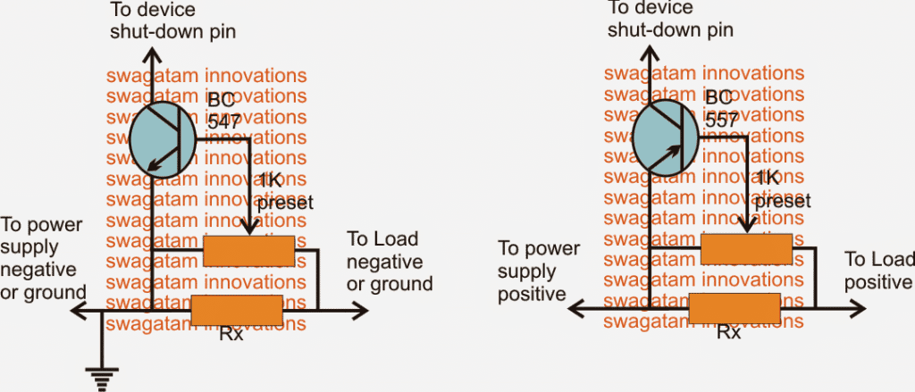
For circuits which may have a ground shutdown feature, the circuit using the NPN device could be employed as shown in figure on left.
Here Rx is selected such that a potential difference of about 0.6V is developed when the amp consumption at the output or by the load tends to go above the marked danger threshold.
The 0.6V is the optimal conduction voltage level for the shown BC547 or any low power general purpose BJT, thus as soon as this level is reached, the BJT conducts and grounds the available shutdown pin, switching of the supply to the load instantaneously, and the process keeps repeating at the threshold making sure the consumption is not allowed to exceed the set level.
Calculating the Sensing Resistor
Rx may be selected with the help of the following Ohms law, and as per the circuit requirement:
R = 0.6/I
The preset at the base may be used for fine-tuning the cut off region.
Circuit Diagram
For Positive Shut-Down Operations
In circuits that demands shutdown from the positive line, the current sensor circuit at the right could be used.
This is exactly identical to its NPN counterpart with its functions, except the polarities which are configured to produce a positive drive for the shutdown pin connected across the collector of the BJT.
Now I have explained a few of the example circuits and ICs which facilitate a shut down feature within its allotted pinouts.
Integrating with IC 555
For IC 555, the reset pin#4, or the control pin#5 can be used as the shut down inputs, the NPN sensor above may be wired up here for the intended results.
Integrating with IC LM317/LM338/LM396
For LM317, LM338, LM350, LM396, the ADJ pin functions as the shutdown pin, again the NPN module would work with these devices for the desired current restrictions.
Integrating with IC 4017/IC4060
ICs such as 4060, 4017 may be stopped from functioning by applying a positive reset voltage at their pin#12 and pin#13 respectively. Thus for these examples the current sensor with the PNP device will suit perfectly for the required amp control.
Integrating with IC SG3525/IRS2453
Other examples include IC SG3524/5 = pin#10, positive trigger shutdown.
IRS2453 full bridge driver = pin#5, latched shutdown, positive trigger (2V)
For opamp protection circuits, the input pin which may be responsible for inhibiting the power device at its output may be targeted as the shut down pin and appropriately wired up with either of the above current sensing modules.

Comments
hello & good day Mr. Swagatam
Thank you in advance for your response.
I want to limit the output current from the power supply to a specific value so it doesn’t exceed the set amount. The suggested circuit only turns the device off. But I want it to stay on and not allow the current drawn from the power supply to exceed the limit.
Hello Mazloumi,
The above circuits will do exactly the same as you want, it will switch off the load only while the current is being exceeded and will instantly turn ON when the current is normalized, and this process keeps switching fast within milliseconds, so the load apereas to be always ON with the desired amount of current passing through it.
can i have i diagram for a circuit that when it reach 100v it will cut off.. for both DC and AC application..
For the 3ph to 1ph inverter you suggested, I would like to fit a circuit that, when 3ph is switched on, the load current increases linearly to the value determined by the load. Can you help me?
Thank you very much! That’s very good idea! That didn’t occur to me
No problem Alex, let me know if you need any further assistance.
It can be perhaps done by setting up the SD pin of the inverter IC with a slow start current limiter stage.
Need to turn the DC motor in both directions.
Can I then couple/link both curcuits parallel together to same motor? Will it function?
Thank You.
No, that won’t work. Are you using a DPDT relay for the reverse forward rotation of the motor??
Thanks Sir. How many amps maximum can the circuit withstand? Or what should I replace for a bigger application?
Hi Onyi, the circuit can be set to any desired current limit by modifying the Rx resistor value
Hello dear swagatam
How can i make an ac adjustable current controller?
Hello Ehsan, you can try the following concept for AC current control
https://www.homemade-circuits.com/mains-over-load-protector-circuit-for/
“Happy Republic Day”,SIR,
It will be fantastic to get a circuitry for “PLASMA ARC”…….Just to build a Fuel less and Flame less LIGHTER,Using a rechargeable li-po/li-ion battery .
Thanking you ,
K. Kausik
Thank you and wish you the same, surely, I will consider it!
Hi, i want to build power supply with a current limiter and voltage regulator. Im going to use LM338T, should i use left diagram or right? and why?
Thanks in advance for your help
Hi, you can use the left side NPN design, since it is easy to configure this with the ADJ pin of the LM338
IC LM338 Application Circuits
Dear Mr. Swagatam,
first off all thank you very much for all the valuable information provided on your Blog. Indeed this is very helpful for beginners and professionals to find the right solution.
For my new project I am looking for a circuit for my application.
Currently I am building a DIY Powerwall which shall be charged by solar modules and if no Sun is available power my house. I do have a solar system installed on my roof which is able to deliver 13,2 kW peak. This goes to a three phase inverter which provides 3 x 220V (living in Germany). Have included a picture of the overall architecture of my design:
[Here shall be a picture of my overall architecture. Was not able to upload that. How can I send you this?]
I do not want to touch the existing system, so I am looking for a coupling via the AC side only.
If the solar system is delivering more power than I can consume in my house, the battery shall be charged. As DC power supply I use 4x AC-DC converters (220V to 10V 120A each) in series. Depending on the delta of solar power produced and power consumed I need a electronic circuit in between the DC power supply and the battery which delivers constant voltage but adjustable (controlled by a microprocessor controlled unit) current (0A- 120A). This circuit shall have not to may losses (heat) and can also be microprocessor controlled (Arduino, etc.). The second Unit I need is quite similar to the first one and shall be connected in between the battery and a stack of microinverters. Here we have a varying Voltage in between 34V- 40V (depending on the charge level of the battery). Depending on the power consumption of the house (sun not shining) it shall regulate the power to the inverter. For the kind of control signal for both units I am quite open as this can be customized in my main control unit.
Do you have any solution for that?
Your help is mostly appreciated. Thanks a lot and have a good day.
Werner
Thank you Mr.Werner for your queries, however I am not a microprocessor or Arduino expert, therefore addressing a microprocessor based design can be difficult for me. Still, I will try to investigate it, and if i find a suitable readymade design online will surely let you know.
Thank you very much for your reply.
Many greetings from Germany
Glad to help!, thanks
Hello sir Swagatam. I was looking for an overload protection circuit for an inverter circuit and you referred me to this post. It appears to be exactly what I need for the intended purpose which is to shut down an SG3525 i.c in an inverter circuit when overload is detected in the transfo output. I’ll have to use the PNP version. Thank you very much sir. But I have some questions:
1. Where should i connect the “to load positive” to? Is it to the inverter transfo 220V output?
2. Where should i connect the “to power supply positive” to? Is it to the battery? If yes, can i also connect it to the output of a12V regulator incase I’m using one to power the driver session of the inverter?
3. How can i choose the correct Rx value for a particular maximum load? Is the method used by mexzony in his comment correct?
Anticipating your usual prompt response. Thank you sir.
Godson, the supply positive side must go the battery positive directly, and the other side to the inverter side positive, meaning the whole power to the inverter must pass through the sensing resistor, otherwise the circuit will fail to produce the intended results.
the formula for the Rx is already provided in the article:
0.6/shut down current
Alright sir. Thank you very much. I really appreciate you.
you are welcome Godson!
hello sir,when i made the circuit pnp type i connected it to pin 10 in sg3524 and ground it with a 47k resistor, but it didnt work, at exceeded rate, it didnt shut down
atinuke, check the voltage across base/emitter of the transistor, it must reach 0.6V to conduct….and also measure the voltage at pin#10 of the IC, it must acquire 5V to trigger the shut down….
Hello sir
Also one thing am bothered with is for the PNP version the power supply positive will be from Inverter output so won't this melt our resistor
Hello sir
Pls how exactly will the preset fine tune the cut off region
For example if using the PNP version
At 220v 1500w we have 1500/220 = 6.8 approx..
Now Rx = 0.6/6.8 = 0.08 ohm approx
So assuming this is connected to the inverter and set up as per the calculations above then when this current exceeds 6.8A how does the preset known to sensitize the circuit.
Basically how does the preset work.
Also if I wanted a delay will just a capacitor at the base /emmiter of transistor work or do we use an RC time constant technique as I may want up to 5 secs max delay.