In this post we learn about this 220V AC electronic fan regulator circuit using a push button which changes speed step by step with each press. We press the button, then circuit cleans the signal, counts it properly, and then selects a relevant fixed speed level. Each button press moves the fan from OFF to low, then medium, then high, and finally maximum, and then it repeats.
Audio/Video Representation
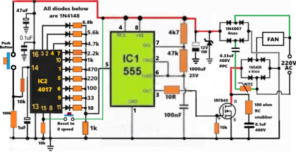
Circuit Diagram
Push Button + RC Debounce Network (Input Stage)
On the extreme left we have a mechanical push button, however problem with push buttons is simple, they bounce. If you press once, the contact shakes, so one press can create many pulses.
Since CD4017 is fast, it will jump steps like mad if you do not control this.
That is why we added debouching parts like 10k resistor, 100k resistor, 1 uF capacitor.
When you press the button, then voltage at pin 14 of CD4017 does not jump suddenly, it rises slowly and clean. So the RC delay absorbs all mechanical noise, but leaves only one clean rising edge.
So, only one valid pulse reaches the 4017, nothing extra, so now, one press equals one count.
CD4017 Decade Counter (Step Controller)
Here, in the IC 4017 stage Pin 14 is the clock input coming from push button network. Each press advances the output, step by step.
The outputs used are Q0 to Q9, depending how many steps you want.
Pin 15 reset is wired such that after the last step, the counter comes back to Q0.
Each of the output corresponds to one fixed fan speed.
So with this setup you get OFF, then Low, then Medium, then High, then Maximum, or whatever combination you choose.
Diode + Resistor Network (Voltage Programming Ladder)
In this setup, each of the 4017 output goes through a 1N4148 diode for isolation, then a resistor. Resistor values are 10, 33, 100, 220, 470, 1k, 2.2k, 4.7k, 5.6k, 6.8k.
Only the active output feeds voltage, all others are blocked by the diodes. These resistor values decides how much voltage reaches pin 5 of the IC 7555.
This behaves like a stepwise DAC, not exactly, but still good enough.
So, lower resistor means lower control voltage, and so low speed.
Higher resistor means higher control voltage, so high speed.
IC 7555 PWM Generator
IC1 which is 7555 is working in astable PWM mode generator.
Pins 2 and 6 are tied together, which is standard practice in any 555 astable configuration. 47k and 4k7 define the oscillation timing.
Pin 5 receives the stepped control voltage from the IC 4017 output ladder stage.
0.1 uF at pin 5 keeps things calm, so that no jittering happens.
In this 555 astable the frequency stays almost constant, but duty cycle keeps changing, depending on which output from the IC 4017 is selected through the push--button operation.
Because of this the fan speed changes smoothly but in steps.
Hence, this works like a true PWM control, not crude chopping like cheap regulators.
MOSFET Gate Drive and Filtering
Now, in the MOSFET control circuit, the Pin 3 output of 7555 goes through a 10 ohm resistor, so that this slows the edge just enough.
The 100 nF capacitor to ground filters sharp spikes. 10k gate to ground resistor makes sure MOSFET stays OFF at reset.
This prevents false turn on, gate ringing, and EMI headaches.
MOSFET Power Stage (IRF840)
In this stage IRF840 is used as the high voltage PWM switch. Now some important detail here, do not miss it.
Here the fan AC is bridge rectified using 1N5408 × 4. MOSFET switches the DC side, not the AC directly, as you can clearly see in the diagram. So this works good since MOSFET likes DC. There's no triac commutation mess, no instability.
Therefore, speed remains stable even at low RPM. Inductive fan load is handled cleanly.
Snubber and Flyback Protection
In the diagram we can see RC snubber across MOSFET, which can be calculated using the calculator given in this article...
Power Supply Section
In this section we make sure that no bulky external power supply is needed to power the 555 and 4017 circuit stages, instead we derive the power directly from the bridge rectifier DC switching of the fan.
The current is taken through a 0.33uF/400V capacitor, and a parallel 10k resistor ensures this capacitor discharges during 0V periods of the bridge rectifier output.
1N4007 diode is there for polarity protection, while the zener is used to stabilize the DC to 12V
100 uF capacitor is there for smoothing and filtering of the DC for efficient working of the circuit.
Overall Working Sequence
When the Push button is pressed, the RC network creates one clean pulse.
This allows the CD4017 output to advance one step, then the corresponding resistor divider network feeds voltage to 7555 pin 5.
Depending on which 4017 IC output hits the divider network, the pin#5 PWM duty cycle changes accordingly.
Because of this specific PWM range, the MOSFET ON time changes accordingly, and we see the fan speed changing.
If you keep pushing the push button until the last 4017 sequence is reached, the 4017 internal counter resets and the output goes back too pin#3 of the IC, so that and cycle can repeat again.
Final Thoughts
- This push button version is more robust than touch version, because of the following reasons.
- This circuit is immune to humidity and EMI.
- Suitable for wall mounted regulators.
- No false triggering is there.
- This resembles an industrial style logic design.
- A proper digitally stepped PWM fan regulator, not just a toy dimmer.

Need Help? Please Leave a Comment! We value your input—Kindly keep it relevant to the above topic!