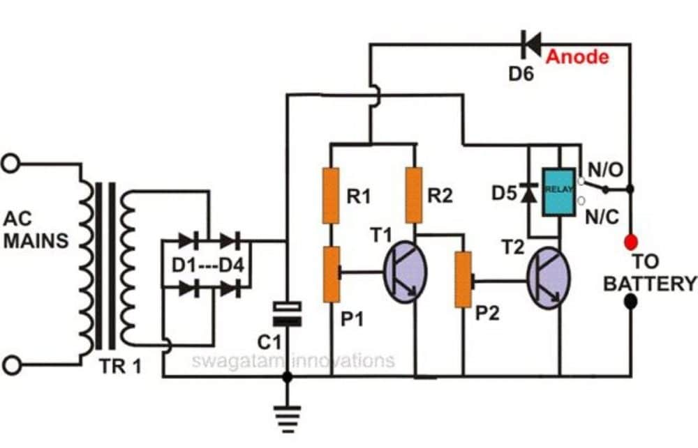
In this post I have explained how a neat little self regulating automatic battery charger circuit can be made using just two inexpensive transistors.
This circuit will automatically regulate the charging supply to the battery depending on its charge level, by switching the input supply ON and OFF periodically.
How it Works
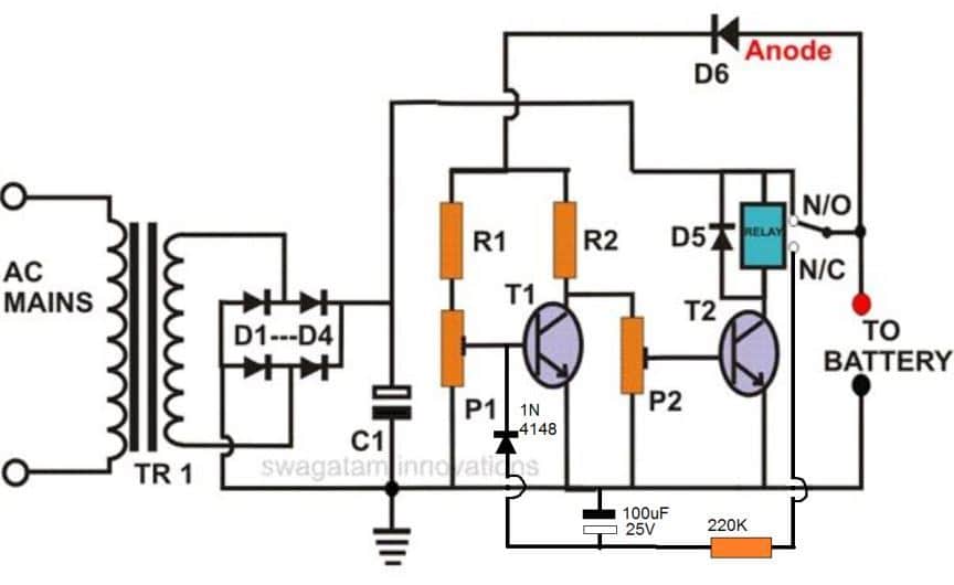
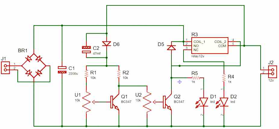
As can be seen in the diagram, this auto-regulating battery charger circuit utilizes just two transistors for detecting the charging thresholds, and cuts off the process as soon as these limits are detected.
Using two transistor actually makes the design hugely sensitive compared to a single transistor charger circuit.
The indicated preset is set in such a way that the T1 is just able to conduct at the specified full charge threshold of the battery.
When this happens T2 begins switching OFF, and ultimately at a point it is unable to sustain the relay conduction and switches OFF the relay, which in turn cuts of the input charging source with the connected battery.
Conversely, when the battery voltage begins dropping, T1 gradually deprived of its adequate conduction voltage level, and ultimately it ceases to conduct, which quickly prompts T2 to initiate its conduction and trigger the relay into action,
The relay now reconnects the charging input supply with the battery, and restores the charging process until it yet again reaches the full charge threshold, when the regulating cycle repeats itself.
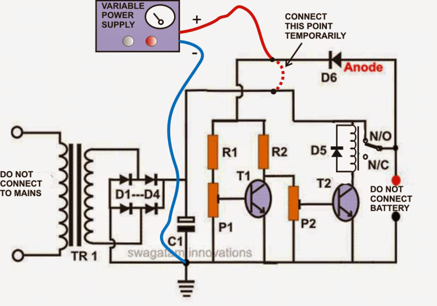
How to Sep Up the Circuit
Setting up this battery charger circuit for automatic regulation is very simple and may be done in the following way:
- Initially, do not connect the fixed transformer power supply; instead connect a 0-24V, variable supply voltage to the circuit.
- Remove the anode of D6 from the relay contact and connect it to the positive of the power supply.
- Keep both the presets somewhere at the center position.
- Switch ON the power and adjust the voltage to 11.5 volts or lower.
- Adjust P2, so that the relay just activates.
- Now increase the volts to about 13.5 volts, and adjust P1 so that the relay just deactivates.
The setting procedure of the circuit is now complete.
Check the whole procedure by continuously varying the voltage up and down.
You may now remove the variable power supply and connect the fixed transformer, bridge power supply to it.
DON’T FORGET TO RECONNECT THE ANODE OF D6 BACK TO THE RELAY CONTACT OR THE BATTERY POSITIVE.
The battery connected to this circuit will be charged only as long as its voltage is in between the above "window" level.
If the battery voltage crosses the above "window", the relay will trip and stop the battery from charging.
Parts List
- R1, R2 = 10K = 2
- P1, P2 = 10K PRESET = 2
- T1, T2 = BC 547B = 2
- C1 = 2200uF/25V = 1
- C2 = 47uF/25V (Please connect this capacitor across the relay coil) = 1
- D1---D4 = 1N5408 = 4
- D5, D6 = 1N4007 = 2
- RELAY = 12 VOLT, SPDT = 1
- TRANSFORMER = 1, (AS PER THE CONNECTED BATTERY AH (DIVIDE BY 5)
The following diagram shows the instructions which needs to be followed while setting-up the circuit with the desired cut-of thresholds, using a variable power supply unit:
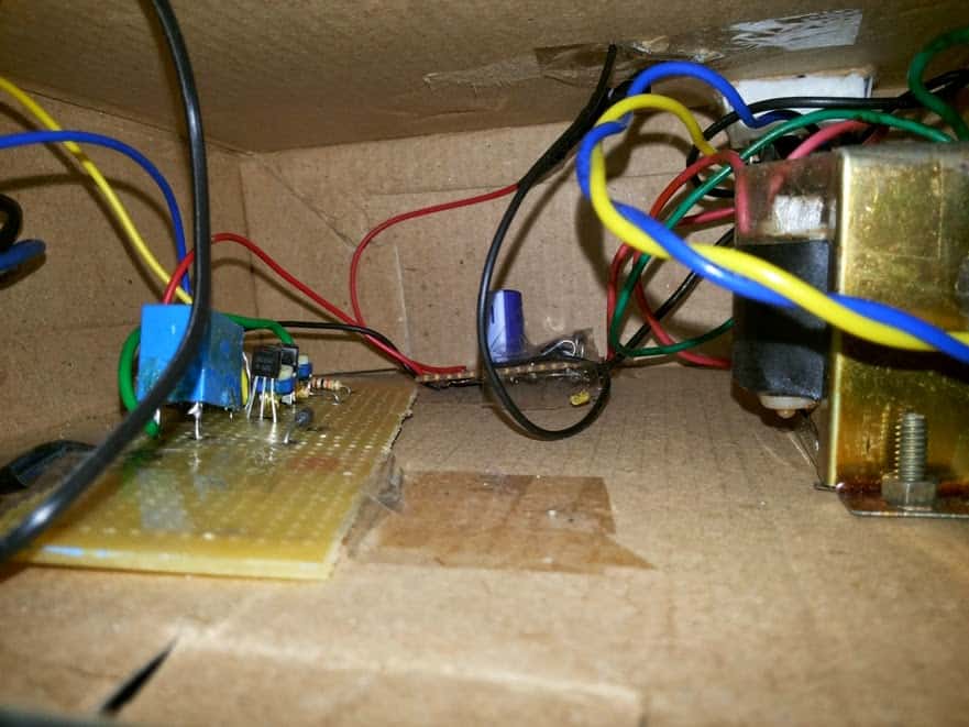
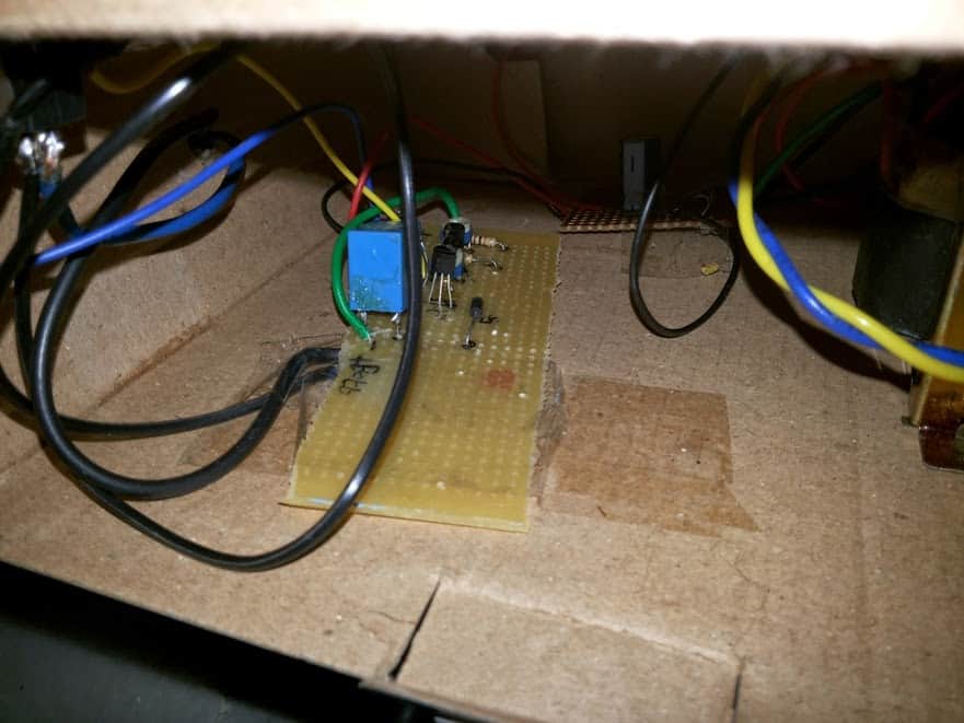
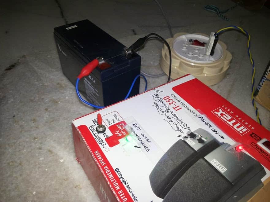
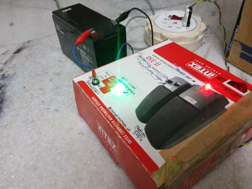
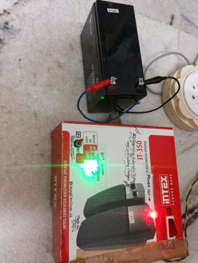
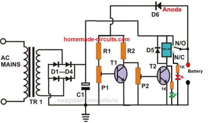
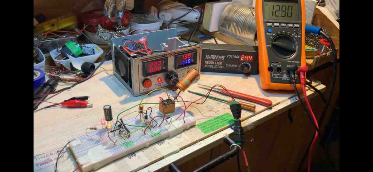
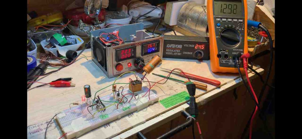
The above self-regulating battery charger circuit was successfully built and tested by Mr. Sai Srinivas, who is just a school kid but nevertheless has an immense interest in the field of electronics.
The following images were sent by him which displays his talent and intense dedication in the field.
For One Shot Operation
If you want the above circuit to lock itself into a permanent cut off position when the battery is fully charged, then you may modify the design as shown below:
Note: To ensure the relay does not latch itself quickly on power switch ON, always connect the discharged battery first across the shown terminals and then switch ON the input power.
In order to indicate the charging status of the battery, we can add a couple of LEDs to the above design, as shown below.
The above circuit was also successfully built and tested by one of the dedicated electronic enthusiasts from this blog. The following pictures verify the results:

Warning: Make sure to test the preset setting thoroughly before you leave this application unattended. And be sure to use only 14V as the input supply for a 12V battery.
Formulas and Calculations
Full-Charge Cutoff Voltage
The voltage at which charging stops is calculated as:
Vcutoff = VBE(T1) + (P1 / (R1 + P1)) * Vsupply
For example:
Full-charge voltage (target) = 13.8 V
VBE(T1) = 0.7 V (for silicon transistors)
Vsupply = 15 V (after rectification and, filtering)
To achieve a cutoff of 13.8 V you can set the divider network:
13.8 = 0.7 + (P1 / (R1 + P1)) * 15
Rearranging for P1 / (R1 + P1):
P1 / (R1 + P1) = (13.8 - 0.7) / 15 = 13.1 / 15 ≈ 0.873
Choose R1 = 1 kΩ.
Then: P1 = 0.873 * (R1 + P1)
P1 = 0.873 * (1000 + P1)
P1 ≈ 687 / 0.127 = ~6.87 kΩ
Set P1 to approximately 6.8 kΩ.
Reactivation Voltage
The voltage at which charging restarts is calculated as:
Vreactivation = VBE(T2) + (P2 / (R2 + P2)) * Vsupply
For example:
Reactivation voltage = 12.6 V
VBE(T2) = 0.7 V (same assumption as above)
Vsupply = 15 V
To achieve a reactivation voltage of 12.6 V:
12.6 = 0.7 + (P2 / (R2 + P2)) * 15
Rearranging for P2 / (R2 + P2):
P2 / (R2 + P2) = (12.6 - 0.7) / 15 = 11.9 / 15 ≈ 0.793
Choose R2 = 1 kΩ.
Then: P2 = 0.793 * (R2 + P2)
P2 = 0.793 * (1000 + P2)
P2 ≈ 793 / 0.207 = ~3.83 kΩ
Set P2 to approximately 3.9 kΩ.
Relay Activation Current
The current needed to activate the relay is:
Irelay = Vcoil / Rcoil
For example:
Vcoil = 12 V (relay coil voltage)
Rcoil = 400 Ω (typical relay coil resistance)
Irelay = 12 / 400 = 0.03 A (30 mA)
Filter Capacitor Value
The filter capacitor smooths the DC and is calculated as:
C1 = Iload / (2 * f * DeltaV)
For example:
Iload = 1 A (charging current + circuit consumption)
f = 50 Hz (mains frequency)
DeltaV = 2 V (acceptable ripple voltage)
C1 = 1 / (2 * 50 * 2) = 1 / 200 = 0.005 F = 5000 µF
Choose C1 = 4700 µF or 6800 µF... for sufficient filtering.
Hysteresis Voltage
The hysteresis prevents frequent relay switching and is calculated as:
V_hysteresis = V_cutoff - V_reactivation
For example:
V_cutoff = 13.8 V
V_reactivation = 12.6 V
V_hysteresis = 13.8 - 12.6 = 1.2 V


Comments
is there any way that it can use only one RED LED.
where if it cut off, the RED LED will be off. without switching or cutting from RED LED to Orange?
Remove the two LEDs shown in the last diagram, and connect a single LED in series with the base of the T2 transistor.
Just stumbled upon your very helpful circuit of self regulating battery charger. Please what is the value and type of the diode used in the alternative circuit without relay I mean the one connected to the base of TIP122? Is it a silicon diode? The circuit was last updated on May10, 2021. Thanks for your kindness.
Thanks for responding. I am referring to the reply you sent to Vee on May I 2021 where you posted an alternative circuit diagram using a diode connected to a TIP 122 transistor to replace the relay and the 2nd transistor in the original circuit, thus making it a solid state self regulating auto cut off battery charger. I tried to copy and send it you but didn’t succeed. Thanks again.
OK, understood. However, after a deeper investigation I realized that this circuit had some issues, so I replaced it with a better alternative.
Here’s the link for the new solid state self regulating battery charging circuit, which you can try:
https://www.homemade-circuits.com/wp-content/uploads/2022/04/simplest-bench-power-supply.jpg
Thank you very much Swagatam. Very happy that people like you are still on this earth. I wish you more knowledge and strength.
Thank you Robert, I am always glad to help!
Hi, thanks, can you please specify which circuit diagram are you referring to?
I cannot see any circuit without a relay…
What is the purpose of C2 ? Will this circuit work without it, and why isn’t shown in the circuit schematic ..?
It is to ensure that the relay does not chatter while switching….it is important to attach this capacitor parallel to the relay coil.
Thank you Swagatam, I thought that’s what D5 was for, but I can assure you I will install that capacitor for good measure ..! Thank you so very much for sharing this circuit, I was trained as a technician and have very limited knowledge of circuit design, thanx again for your help, best regards-Mark
You are welcome Mark, D5 is for shorting out the reverse voltage spikes generated by the relay coil and thus prevent the transistor from getting damaged. For C2 please make sure to use a higher value capacitor such as a 220uF or a 470uF which will ensure smoother switching of the relay. Wish you all the best!
Thanx for the capacitor values and I really appreciate your lightning ⚡️ fast response ..!
I am glad to help!
greetings…!!!!
Hi dear Swagatham,
Its so inþeresting your circuit.Regarding the first circuit once the max chaeging voltage reach the relay will cut off then when will start the charging automatically again?ie..when 13.8volt set to cutoff then termiñal voltage become low then will it start immediately hence chance for a chattering relay.can we adjust the lower threshold (the point which charging voltage to start again )in any way?expecting your valuable advice.
from Kerala with ❤❤
Thank you Sison, The relay will not chatter actually, rather switch ON/OFF within a span of maybe 4 or 5 seconds.
The switch ON threshold can be perhaps increased by adding a hysteresis to the circuit.
I have tried this through a feedback link, as shown in the second last schematic.
Owkey sir thanks to reply me!!!
But could u send me your whatsap contact so that u can see easy what I did. Because I used 10K pot which is 103 is real it is exact pot needed? If possible please
Sorry Kadama, providing watsapp number may not be possible. 10k pot will not work correctly, instead you must use a 10K preset, preferably a multiturn type.
you ask me: how many volts and amps is the input source, how do I connect the capacitor C2 that I don’t understand, can you guide me? I really need this, thank you
Input V and I of the supply will depend on the battery specs. Connect C2 in parallel with the relay coil or D5….positive of the C2 will go on the positive supply line, and negative of C2 will go to the lower terminal of the relay which is connected with the transistor collector
I drew the circuit of the battery charger to disconnect automatically according to your diagram, can you check it for me, my battery is 12 volts and 7.5 amps, thank you
C2 must be connected parallel to D5, not D6….the relay connections look messy so I cannot comment on that!
my battery is 12 volt 7.5 amp, so what is the V and I I use, I drew the circuit, I sent it to your email, can you check it for me?
You can use 12V, 1 amp transformer, which will produce around 16 after full bridge rectification. Sorry, I do not communicate through email, if you are having problems with the above schematics please specify about it here.
hi, I drew a printed circuit using Proteus software based on your schematic, I want to send it to you to check for me but it doesn’t work, my source is 15 volts 7.5 amps, now I want to charge it what to do for my battery, thank you
Hi, I cannot suggest about the Proteus results, but practically the circuit works nicely, I have tested it, and many others have also tested it successfully. However if you want an easier op amp based design I can also provide that
Na lista de peças fala em C2, mas não é indicado no esquema. Agradeço indicação como ligar.
Obrigado
You must connect C2 across diode D5 or the relay coil. positive of the capacitor will go the cathode of the diode D5, and negative of the capacitor will go to the anode of the diode.
Hi Swagatam
I managed to play around with the above circuit and got the switching – off to on – to about 1 minute 35 secs approximately by adding a 2200 mfd capacitor across the relay and a 1000 mfd across the base emitter of T1 and a 100 mfd across base emitter of T2. So now its not like fast flip flop.
From a discharged level battery it charges up and cuts off at about 13.0 volts and then cycles between 12.55v to about 12.92v.
And I also changed the connections a bit on the Relay. I connected the Common to the positive of the relay and NO to the battery, works fine.
I tried sending you pictures of the project to your email but got a failure reply saying this email does not exist.
Thanks for all your guidance and help, hope you find this ok
Please reply
All the best till the next time
Regards
Vee
Thank you Vee, appreciate your kind feedback
Glad to know the circuit is working OK for you now!
You can send the images to hitman2008 @ live . in
Thank you very much Vee…got all the images, and I will soon publish them all in the above article.
Hi Swagatam
I must thank you immensely for all the help and guidance you have given me and for your precious time and patience.
Im so blessed to have you as a friend in this field of electronics for which I only as a hobbyist have a passion even at this old age,to pass my time in these crazy times bless you,
Thanks for also sending me an alternative circuit which I would try when I am able to get the TIP 122 . Is this also a SELF REGULATING or AUTO CUTOFF
Thanks again Swagatam
All the best to you
Can I send you a picture of my project by email to you, please let me know ok
Vee
Yes definitely….you can send the pics to my email…hitman2008 @ live . in
It is my pleasure Vee, I am always happy to help.
Yes the transistor circuit would work exactly like the relay circuit, but without making any noise, it would silently keep doing the flip flop switching at the battery full charge threshold, and make sure the battery never gets overcharged…
Hi Swagatam
Good news
I managed to get the circuit working finally the only thing is when adjusting the cut off voltage and cut in voltage it keeps switching on and off like a flip flop so fast when I switch off the power supply and back again then its stable but it happens now and then
I added the caps between the base and emitter of the transistors
I know it takes very minute adjustments of the presets
I has to discharge the battery several times down to about 11 volts and try and it recharged quite fast with the power supply I have, recharges at 1.15 to 1.2 amps and goes down to about 250 ma in about half an hour to 13.8 volts
Thanks again for all your help
Regards
Vee
That’s great Vee, at least you could get the circuit to work ON/OFF at the threshold.
If you connect a 1000uF right across the relay that might prevent the relay from self regulating too fast.
Alternatively you can completely get rid of the relay and use only the transistor stages to charge the battery in a solid state manner….here’s the modified diagram for you:
You can replace the T2 with a TIP122
Hello swagatam.
Can you write how to make the settings of the transistor circuit?
Hi Suat, the setting procedure is the same as described in the article.
Hi Swagatam
I know you said the relay connections are exactly as shown in the diagram but I am a little confused with the labelling as you only show NC & NO & not the C
So I want to know if the connection to the battery and the anode side of the diode is on the NO side of the relay and the Common is to the positive side of the relay
Please reply
Thanks
Vee
Hi Vee, the common pole of the relay is connected with the battery positive and the anode of the diode D6, the N/O of the relay is connected with the positive supply line of the circuit. The N/C point is blank.
Hi Swagatam
Thanks for your reply shall do as you have told me
The car battery is 640 Cold cranking amps Reserve is 85 Amps
The Power supply is a variable 4.5 volts to 24 vdc 2amps I also have a 3 Amp one Its set to 14.0 volts
Are these ok or do I have to have higher amps power supply
I tried these power supply with a Auto cutoff circuit of yours using a BC547 or 2N 2222 and the battery charges well intially at about 1.2/1.3A and slowly reduces to about 200 ma and cutoff when the battery is at 13.8 volts , works good
But I am curious to see how this SELF REG. circuit works …… anyway shall try again aa you instructed me
Thanks Swagatam for your help
Vee
Hi Vee, for a 85 Ah battery 2 amp current is too less, and it might take at least 24 hours for the battery to get fully charged.
The above circuit was tested by many of the visitors successfully so the circuit will work although it might require some skillful adjustment of the presets.
Hi Swagatam
I tried the above circuit (self regulating charger) but I still could not get it working
Is the common contact of the relay connected to the anode of the diode and the positive power supply connected to the NO of the relay
When I tried doing the initial settings as per your instruction there is no response on the relay.
I am using a 12 volt cube relay whose coil resistance is 410 ohms
I also tried transistor BC 547 and also 2N 2222 ( pinout is opposite to 547)
Power supply is from my variable bench supply set as per your instructions
Please help
Vee
Hi Vee, yes the relay connections are exactly as shown in the diagram.
You can set up the circuit in the following way.
Keep the slider of both the presets to ground.
Switch ON transformer supply, and then connect a discharged battery to the relay contacts as shown in the diagram.
Now slowly adjust P2 until the relay clicks ON….now the battery will start charging.
Monitor the voltage with a voltmeter until the battery is fully charged.
As soon as the battery is fully charged, slowly adjust the P1 preset until the relay just clicks off.
Your setting up procedure is now complete.
Connect a 100uF capacitor across the base/emitter of both the transistors to stabilize the relay contact operations.
Remember the transformer current must be 10 times less than the lead acid battery Ah rating.
Thank you Odon, I appreciate your thoughts very much!
hello sir swag in any case I thank you for your bravery of the design of several electronic diagrams which opens to several people the eyes to read the diagram
Dear,
please help me 3000 VA online inverter simulation circuit, 1minute backup,200Ah,with automatic charger circuit simulation Proteus software send me my email. Thanks
B.Sc. in EEE,
Kadama, you will have to use a good quality preset and do the steps as explained in the article with proper understanding, it will surely work.
Hello sir I made the circuit as per your schematic diagram but while I’m setting a cut off full voltage P 1 it can’t deactivate the relay
Hi Vee, you can put your LM317 questions under any of the following articles:
https://www.homemade-circuits.com/?s=LM317