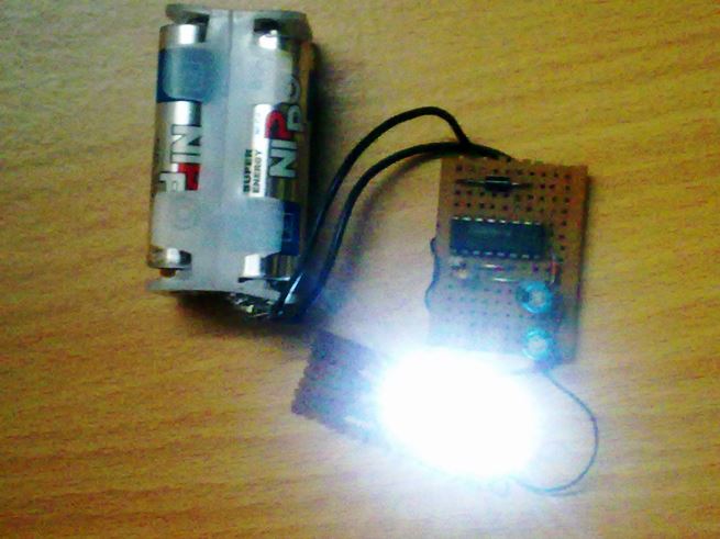
A simple LED torch circuit that would light up 3 white LEDs from a 6 volt supply and would make your battery last forever is described here. A useful voltage doubler circuit is incorporated here to make a highly efficient circuit using just a handful of components. Introduction Learn more how to build it. White […]
Search Results for: IC 4049 circuits
7 Easy Voltage Doubler Circuits Discussed
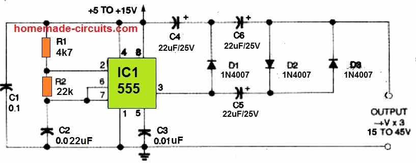
In this article I have explained 7 easy to build DC to DC voltage doubler circuits using a single IC 4049 and IC 555 along with a few other passive components. If you are wondering how a simple IC 555 can be used for making a powerful voltage doubler circuit, then this article will help […]
5 Simple Water Level Controller Circuits
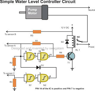
An automatic water level controller is a device which senses undesired low and high water levels in a tank, and switches a water pump ON or OFF accordingly to maintain an optimal water content in the tank. In this article I have explained 5 simple automatic water level controller circuits which can be used for […]
NAND/NOT Gate RC Values Calculator
In this calculator, instead of entering resistor and capacitor values, you give target frequency, like 500 Hz or 1000 Hz… Then what the calculator does: Rearranged to: This is super useful when you want to hit some exact blinking rate, beep, tone or timer pulse. This Calculator will give you: Works for: Reverse NAND/NOT Oscillator […]
NOT, NAND Gate Frequency Calculator
Here we will learn how to use a NAND Gate Oscillator Calculator using CD4011 or any CMOS NAND gate IC. This calculator will take values of: NAND Gate Oscillator Calculator Calculator by homemade-circuits.com NAND Gate Oscillator Calculator Resistance (R) in ohms: Capacitance (C) in µF: Calculate Here is how this NAND oscillator actually works. We […]
Monitoring 220V AC Load Current using Current Transformer [Circuit Diagram]

In this post I have explained a circuit which can be used for monitoring or controlling AC 220V load current by sensing the load current through a contactless current transformer. Figure 1 below depicts a circuit diagram designed for a non contact load current sensing through a current transformer, which seemed to work well. It is […]