In this post we are going to see how we can construct an RGB LED light strip controller circuit for PC cabinets and also for general decoration purposes. In this post we will construct a couple of RGB light strip controller designs, one for a PC cabinets and one for general purpose which can be operated using any IR remote and push buttons.

RGB LED light strip overview:
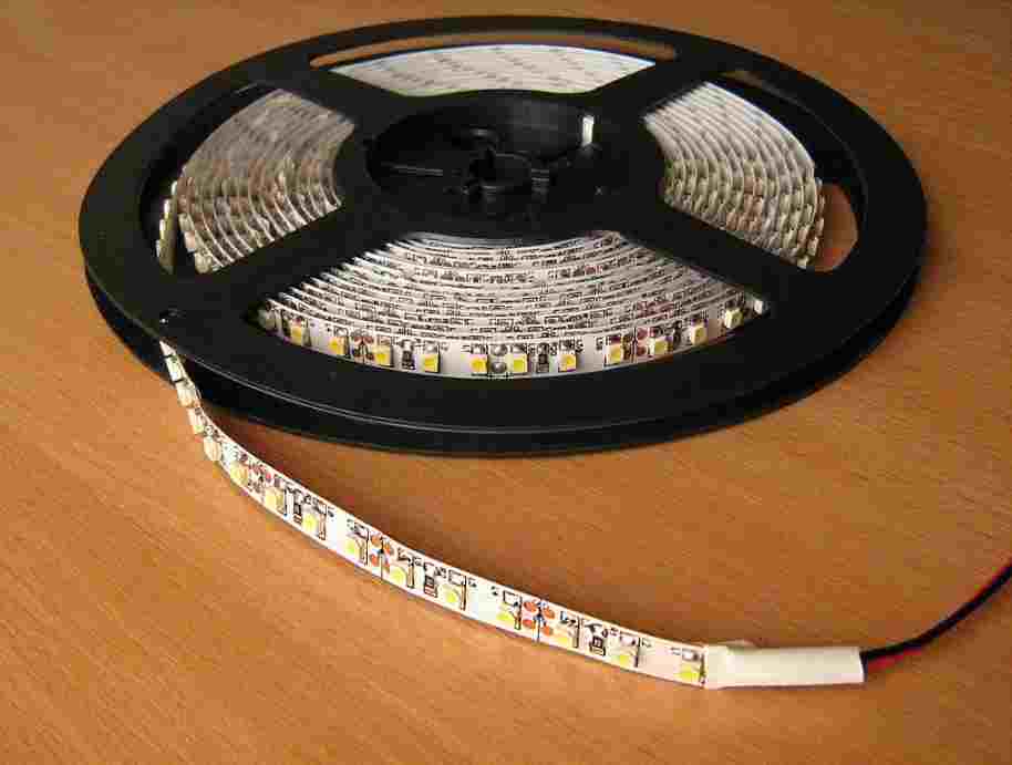
LED light strips are long flexible PCB (with sticky back) with RGB LEDs soldered on it; they can be cut into different lengths as we wish and can be powered with the same voltage regardless of the customized length.
There are single colored and multi-colored LED light strips. A single colored light strip contains only one color LED, obviously and doesn’t need a control circuitry unless you want it for flashing or controlling brightness.
The most common light strips are multi-colored RGB and RGBW; RGB light strip contains red, green and blue LEDs and RGBW consists of one additional pure white LED, because achieving white color by mixing RGB may not always look pleasant. RGB LEDs illuminate together with different brightness to achieve several different colors that individual LEDs cannot. The RGB light strip requires a control circuitry.
PC cabinet RGB strip controller circuit: Static illumination
The proposed circuit is segregated into multiple sections for better understanding and illustration. The proposed RGB controller for the PC cabinet can illuminate 7 different colors and after the 7th color the strip turns OFF. The circuit shown below is responsible for selecting an illumination color.
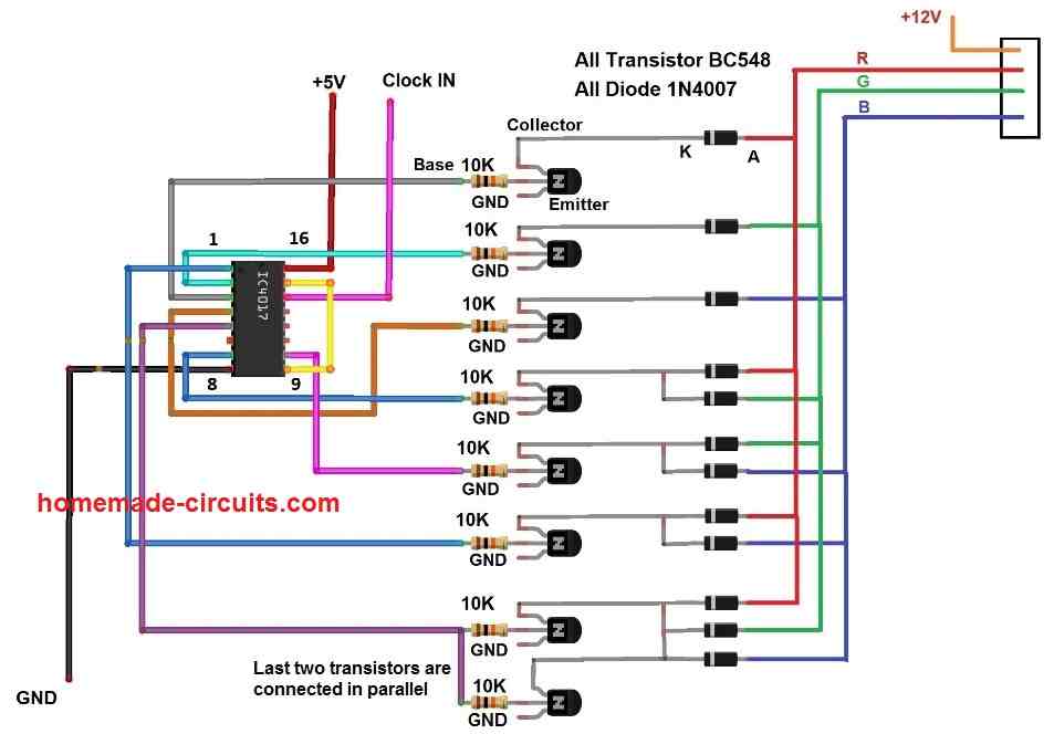
The above circuit consists of IC 4017, bunch of NPN transistors and diodes which are connected to a RGB LED strip. An IC 4017 is employed, which is a Johnson decade counter which can count from 0 to 9 (it can make its output sequentially HIGH according to the incoming clock pulse).
The outputs of IC 4017 are fed to the base terminal of the transistors which will turn ON and OFF specific LED color of the light strip. We can also see there are a bunch of diodes connected to collector terminals, this is for selecting multiple LEDs simultaneously to generate a new color and also to prevent current passing to inactive transistors which will light up unwanted LEDs.
The last two transistors are connected in parallel to create white color, since it needs to illuminate all the LEDs in a strip which will demand a larger current. If you have an RGBW light strip you may connect the last transistor to white LED terminal.

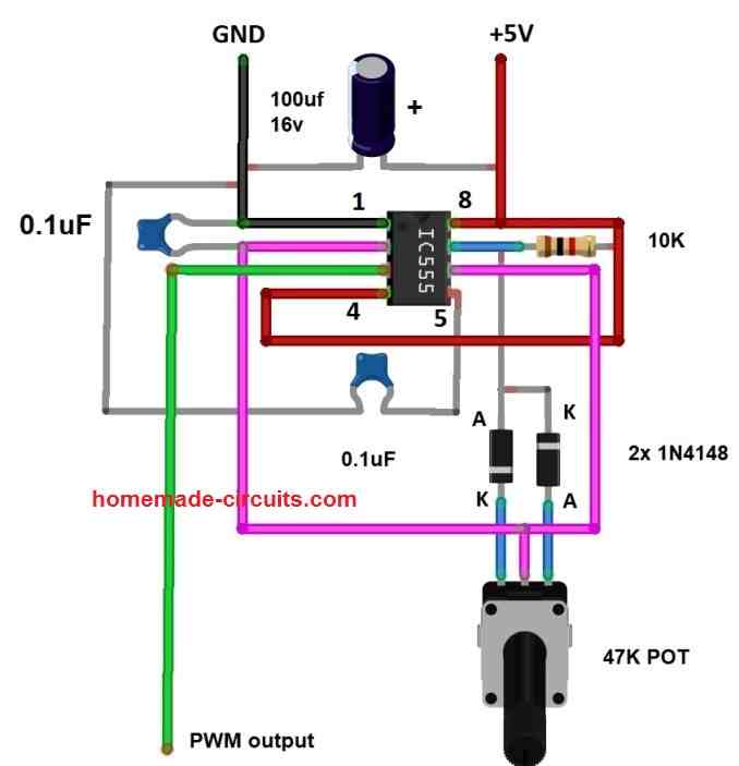
The above circuit is responsible for providing a proper clock signal to IC 4017 which in turns changes the LED illumination color. The above circuit is a monostable multivibrator / debouncing stage which takes a (noisy) negative pulse from the push button and gives out a clean HIGH signal for a pre-determined period of time, so that the IC 4017 won’t register multiple button presses or skip some colors.
A potentiometer is provided to adjust the output timing and please try to keep the pulse at pin #3 between 0.5 to 1 second for optimum operation.
Incorporating brightness control:
Many PC enthusiasts will love to have brightness control for their RGB light illumination, using the below shown circuit modification one can achieve variable brightness control.
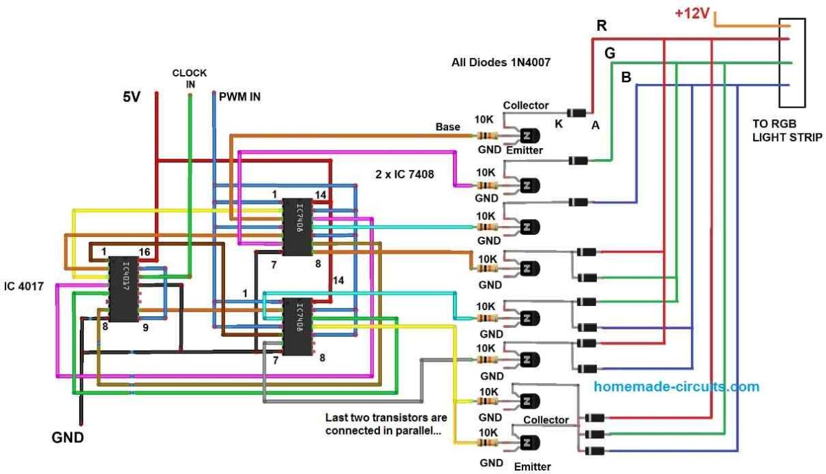
The above circuit is employed with a couple of logic AND gates, the upper one controls the upper four transistors and lower AND gate controls the rest of the three transistors. One of the inputs of all AND gates are tied together and connected to a PWM source. The other inputs of all AND gates are connected to IC 4017’s output for selecting an illumination color.
NOTE: Please note that the above circuit also needs the debouncing stage for button input.
PWM source:
The above circuit generates a PWM signal which will be fed to AND gate. By adjusting the provided 47K potentiometer you can adjust the brightness of the LED strip.
Running light for PC cabinet:
If you are not a fan of static illumination of LED light strips, you can try this circuit which flashes red, green and blue.
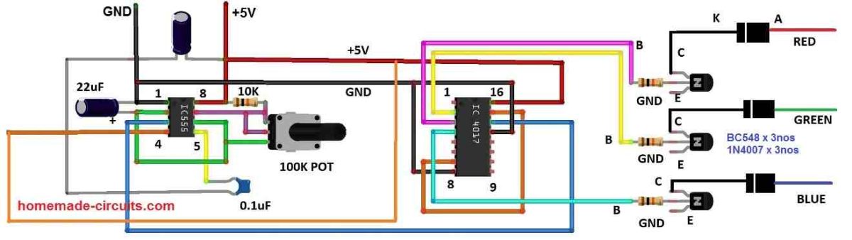
The circuit is very easy to build; it has an astable multivibrator using IC 555 and IC 4017 to flash between red, green and blue. The astable multivibrator circuit generates a steady clock pulse which is fed to IC 4017. Every time when the IC 4017 receives a clock signal the output will be switched to a new color.
You can set how fast switching of RGB color you want by adjusting the 100K potentiometer.
Incorporating brightness control:
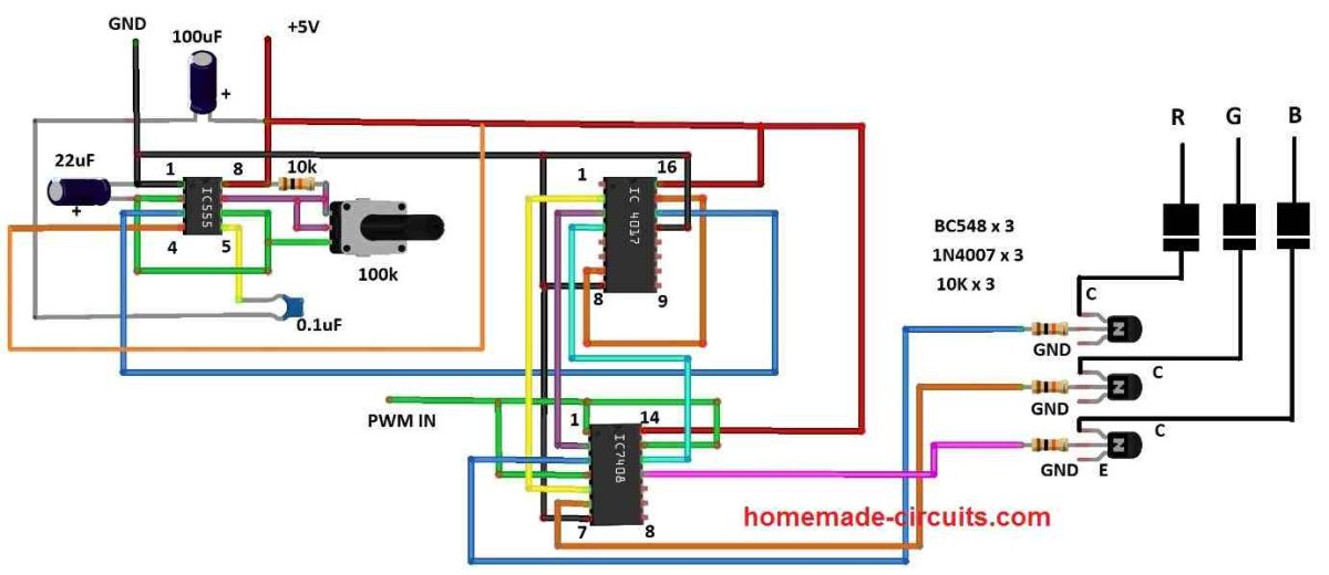
The above circuit is same as the previous one, only the difference is the addition of logic AND gate. There are four AND gates in the IC 7408 and we are utilizing three of them. One of the AND gate input of all three gates are tied together and connected to a PWM source and the other three inputs are for selecting illumination color.
IR controlled RGB light strip: (for general purpose)
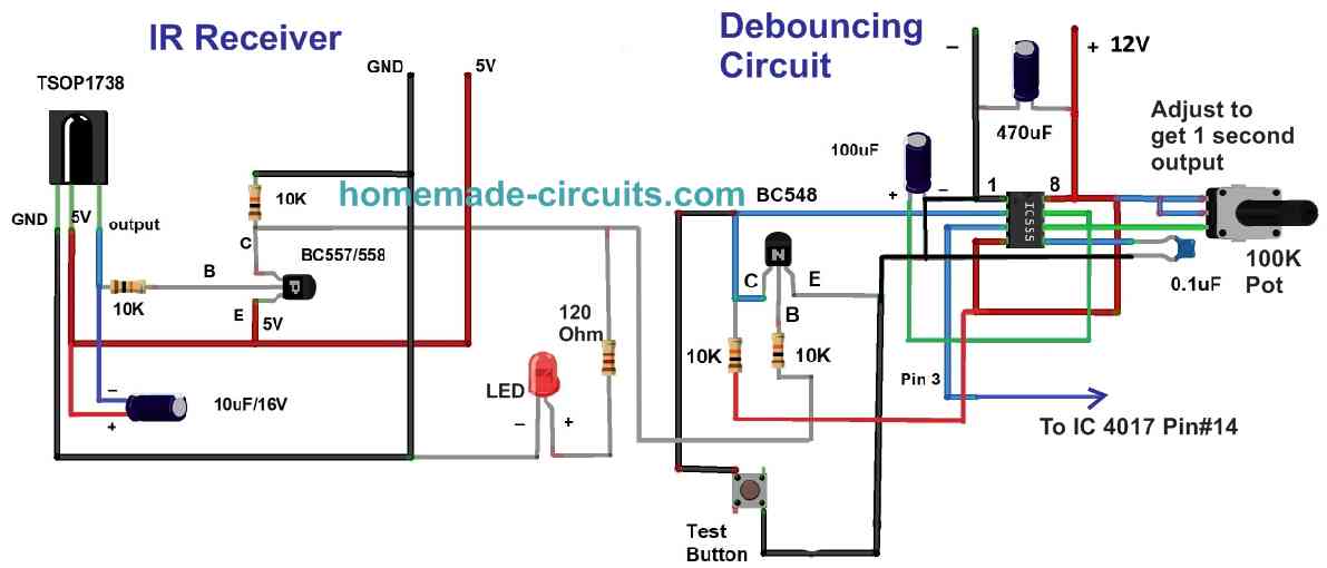
The above circuit is an IR receiver stage which can detect IR signals from any commonly used IR remote controllers.
When an infrared signal is targeted towards the circuit, the incoming signal will be picked by TSOP1738 and converted to pulsating electrical pulses; the pulses are encoded with information which is irrelevant for this project, so we are using a capacitor to smooth it out.
The output after smoothing is feeble and needs amplification, to accomplish this we are using a low power PNP transistor. A LED is connected to the IR stage which indicates that the IR signal has been detected.
The amplified output is fed to a debouncing circuit which gives out a steady HIGH signal to the next stage. The purpose of debouncing circuit is to pick the received signal from the IR stage which could be noisy and gives a smooth output signal, thus noise and unintended multiple button clicks are eliminated.
The clock signal from the debouncing stage is fed to pin 14 of IC 4017 which will switch the light strip’s illumination color. By pressing any button on the IR remote you can switch to your desired illumination color, after white color which is the last one you can turn off the LEDs in the light strip and by pressing a button on the remote we can cycle through all the colors again.
How to smoothly transition between colors?
We can smoothly transition between Red, Green and Blue colors by utilizing a capacitor with appropriate values (220uF to 1000uf) connected to the collector terminal and +12V. This will eliminate abrupt change of colors and also looks pleasant to our eyes.
Note 1: The control circuitry works on 5V and the LED light strip works on 12V, meaning you need a dual power supply.
Note 2: If you are decorating your PC cabinet with RGB, do not power the control circuit or the RGB LED strip from the computer's SMPS, power it from an external wall adapter.


Comments
Hello Swagatam,
Do you know of any ready made controller ICs which are used in commercial controllers like SP104E or SP105E and other similar very inexpensive controllers which are currently available in the market or are they made of these basic ICs like 4017 and 555?
I am thinking that they are made of dedicated ICs for lower cost advantage but cannot find much details regarding the same. I know we can achieve all the functionality using ESP 32 and other similar ICs but they are more expensive than the total package costs of these controllers currrently available in the market for Rs 80 or less.
Thanks
Abhi
Hi Abhi, sorry, unfortunately I do not have any idea about these ICs since I have never used them, I normally design circuits using discrete ICs and parts only.
Hi Swagatam;
I will use strip led lights in single color. As I searched the market the problem is that the transformers in higher current capacity are too expensive.
I think that the strips I will use have the current capacity 0.5 Amps in 1 meter length. If we use 10 meters of the strips that means we need over 5 Amps transformer. So I need your advices on the following subjects.
A) If it is possible to use AC 220 V for 10 meter strips instead of DC transformer / adapter?
B) Another sample is: For instant, I will use separately 3 pcs of the strip leds as 1 pc of 60 cm and 2 pcs of 20 cm (totally 1 meter of strip lights total current is 0.5 Amps) on a single panel board. I can connect them either serial or parallel and please advise if it is possible to use AC 220 V to light them without DC transformer.
Best Wishes
Hi Suat,
There’s no other alternative other than a transformer or an SMPS. It is not possible to get a high current of 5 amp without using a transformer or an SMPS.
Hello Swagatam
I would like to ask if it is possible to adapt any of the proposed circuits, to control an RGB led light from an old scanner?
The intensity of the light should be adjustable, should allow the progressive adjustment between the different colours in a fixed way.
Thank you in advance,
Best wishes
Hello Joao,
Yes they can be used, if your LEDs are rated at around 12 V.
You can also try the manual method using the following concept:
https://www.homemade-circuits.com/rgb-led-color-mixer-circuit/
Hi Swagatam, thanks for your reply.
Regarding the RGB LED, taken from the Scanner of an Inkjet printer, I don’t know what is its maximum working power and Intensity.
What I do know is that:
– It is common anode and starts to light up with 3 VDC and I tested it up to 9 V, soldered on the original PCB;
– It is quite small and has a shape that resembles a boot;
– It is approximately 1 mm thick and 10 mm high with its 4 pins in line;
– It has a micro inscribed code 7909AH77, on the side that projects light, (it was not possible to find any reference/datasheet on Google);
– Does not have any heat sink;
– It has attached a light-conducting rectangular bar, approximately 3 mm thick and about 225 mm long, possibly made of acrylic.
I suppose I’ll have to remove it from the PCB, to test it on the test board and connect resistors to its terminals, but I don’t know how.
Could you tell me how I should do it and with what values?
Thank you in advance,
Best wishes
Hi Joao,
If its illuminating at 3V, then probably the LED modules are rated to work with 3.3V supply optimally.
If you intend to use a supply higher than 3.3V then after removing them from the PCB you may have to connect a resistor as per the following calculations:
R = Supply input – 3.3 / LED current
If you use 3.3V supply input then no need of any resistor.
Hello Swagatam, thank you for your reply.
My question is about the correct way to connect the Current Limiter Resistor to this common anode RGB LED.
a) Does each color need a separate resistance?
b) A single resistance in the anode, calculated as if 3 LEDs in series?
c) both, a) and b)?
To use a supply of 5 VDC, How will be the control and supply circuit, to have the functions mentioned earlier “The intensity of the light should be adjustable, should allow the progressive adjustment between the different colours in a fixed way.
”
Does equipment like a “Tweezers Digital Multimeter SMD Tester” can show me the correct voltage of the LED?
Can I upload a photo of that RGB LED and how?
Thank you in advance,
Best wishes
Hello Joao,
Each color will require a separate resistor.
3 LEDs cannot be in series otherwise you cannot adjust their intensity separately and progressively.
For adjusting the intensity of each LED color progressively you can try the following circuit
https://www.homemade-circuits.com/rgb-led-color-mixer-circuit/
You can send the image to contact @ homemade-circuits.com….I will check it out.
I have never used Tweezers Digital Multimeter SMD Tester, so not sure about its working.
Hello Swagatam, thank you for your reply.
Analyzing all proposed circuits I came to the following conclusions (please correct me if I’m wrong):
a) To regulate the light intensity, I will need to use 1 “pwm source” circuit and connect it to each of the “5 V input”;
b) To mix the colors I will need 3 circuits of the type “Simple RGB Color Mixer using Transistors”, one for each color.
But now I ask the following question:
Due to my RGB LED being common anode (+), I cannot connect it to GND nor use the same type of transistor proposed in that circuit. Am I correct? if so how will the circuit be for this use?
Thank you in advance,
Best wishes
Hello Joao,
According to me PWM control is not required. The intensity is automatically controlled by the variable voltage regulator using LM317 or using transistor regulator. Just make sure to add a current limiting resistor with each LED.
For transistor intensity controller you can try the following concept for your common anode LEDs
https://www.homemade-circuits.com/wp-content/uploads/2023/03/transistor-LED-controller.jpg
Hello Swagatam, thank you for your reply.
Unfortunately I don’t understand how to connect the 4 terminals of the common anode RGB LED, with all the proposed circuits.
I just need a simple circuit to power an RGB LED predictably at 3V, 20 mA, per color, with a 5Vdc power supply. In which the light intensity must be adjustable, it must allow progressive adjustment between the different colors in a fixed way.
I’m just a curious person for electronics, the DIY type.
When you have the opportunity, can you suggest a inexpensive complete schematic, with all connections for this type of LED.?
Thank you in advance,
Best wishes
Hello Joao,
The BJT circuit which I suggested earlier is exactly as per your requirement. It will control the color intensities of a common anode LED from zero to maximum using transistors.
You will need three such circuits to control your 3 LEDs.
However for the connecting you LED with any circuit, you will have to first identify the anodes, cathodes of your LED module without which the connections may not be possible.
I have no idea about the LED that you are referring to, since I have never used it practically.
Hello Swagatam, thank you for your reply.
I never intended to doubt the proposed schematics, since I know very little or nothing about electronics.
If this was understood as such, please accept my apologies…
My doubt always had to do with the connection of each of the circuits to the various terminals of the RGB LED.
a) Is “my schematic” attached correct?
b) And now where am I going to connect the circuit and which one, to adjust the intensity of the light emitted by the whole set?
Can you please correct what is wrong, and indicate what is missing to include?
Thank you in advance,
Best wishes
No problem Joao,
I just wanted to say that the PNP transistorized circuit which I sent earlier will do the job for you, it will enable you to control the intensity of the 3 LEDs progressively. But you will need 3 separate circuits for the independent adjustments of the 3 LEDs.
Yes your common anode RGB LED schematic sent in my email is correct.
You can connect the RGB LED with the transistorized controller circuit in the following way:
https://www.homemade-circuits.com/wp-content/uploads/2023/03/RGB-LED-intensity-controller.jpg
Hello Swagatam, thank you for your reply.
I would like to know if I can use the suggested circuit of “Variable power supply” to regulate the light intensity of the set of 3 LEDs, which form the RGB LED?
a) If yes, as I don’t have the 8050 transistor, I can use one PNP, like the BC 546B; 547B or C; 548B or C or even BD135?
b) Is it necessary to use some tipe of diode in the connection of the “power supply” to the “RGB-LED-intensity-controller”?
c) For the “transistor LED controller” circuit, Can I use any PNP, like BC557C; 558C or 636?
Is “my schematic” attached correct?
Thank you in advance,
Best wishes
Thank Joao,
Your schematic is correct:
https://www.homemade-circuits.com/wp-content/uploads/2023/03/RGB-controller-with-variable-power-supply.jpg
For the NPN transistor I would recommened a TIP122, BC547, 546, 548 can handle only 100 mA therefore not suitable.
The diode can be removed, it is not compulsory. If you decide to add one then use a 1N4007.
For the PNP transistors I would recommened using 2N2907…BC636 will also work.
Hello Swagatam, thank you for your reply.
Unfortunately at the moment I don’t have any “TIP (Darlington transistor)”, I only have “BD135,139 and the 2N3055)
I will need to purchase some.
Thank you in advance,
Best wishes
OK, no problem Joao, I think a BD139 should work, you can try that!
Hello Swagatam, thank you for your reply.
I will try it out shortly.
I’m thinking of buying a DC clamp meter.
Do you have any suggestions?
Thank you in advance,
Best wishes
Thank you Joao,
Hope it works for you.
I have not yet investigated or used a DC camp meter, so I am not sure about any recommendations.
All the best to you!
Hello Swagatam, thank you for your reply.
What about multimeters, any suggestions?
Thank you in advance,
Best wishes
Hello Joao,
According to me the multimeters that are not very cheap but also has a frequency, capacitance and inductance measuring facility are the good ones and recommended.
Hello Swagatam, thank you for your reply.
Best wishes
You are welcome Joao!
Hola, SWAGATAM, permíteme hacer una sugerencia: en lugar de una fuente doble se puede utilizar un 7805 para obtener los 5v. Saludos desde ARGENTINA.
Thanks Beto, for your valuable suggestion! Noted!
Very Nice. Thank you Bro
My pleasure Hary!
Have any of the members or posters of “Homemade Circuit Projects” ever seen or constructed a collision avoidance type radar system that operates similar to those in automotive use presently. We have a non-automotive application requirement to provide audible notice of a a structure, typically 10-20 yards ahead. If anyone is aware of such a circuit, hopefully simple, please let us know. We would try one from an automobile but the fully integrated systems seem difficult to adapt.
Thank you for your reply and help